PRINCIPLES OF OPERATION
The ranging amplifier is an inverting amplifier comprised The input to the inverting amplifier is always positive and
of two amplifiers; U38 and U39. Amplifier U38 is a low
thus, the output is always negative. In order to facilitate
noise, low offset voltage, chopper stabilized amplifier that a f output, the negative output of the amplifier is routed
is responsible for the precise output of the composite
through an “H” bridge comprised power MOSFETs Q5
amplifier. Amplifier LJ39 buffers the output of U38 pro-
through Q8. For positive (+) polarity, 45 and Q7 are on,
viding the 2OmA of drive needed for the 2OmA range.
and for negative (-) polarity, 46 and Q8 are on.
Components C36, C37, R39 AND R41 serve to stabilize the
composite amplifier circuit.
Table 7-1. Voltage Source Ranges
Range selection is accomplished by turning on the ap-
propriate range FETs Q9 through Ql.3 (see Figure 7-5). A
range FET is turned on by connecting its gate to ground.
Table 7-1 defines which range FETs are on and and which
feedback resistors are selected for each voltage range.
Capacitors C31, C32 and C33 provide additional filtering
for the inverted output. Resistor IGO isolates the output
of amplifier U39 to prevent instability introduced by large
capacitive loads. The simplified circuit of the composite
ranging amplifier is shown in Figure 7-6.
Amplifier Range FETs Feedback
Range Gain On Resistor
200mV 150
Q9, QlO
R36llR38
2v i5
QZ QW
R36llR37
20 v x2 ’
QlO
R36
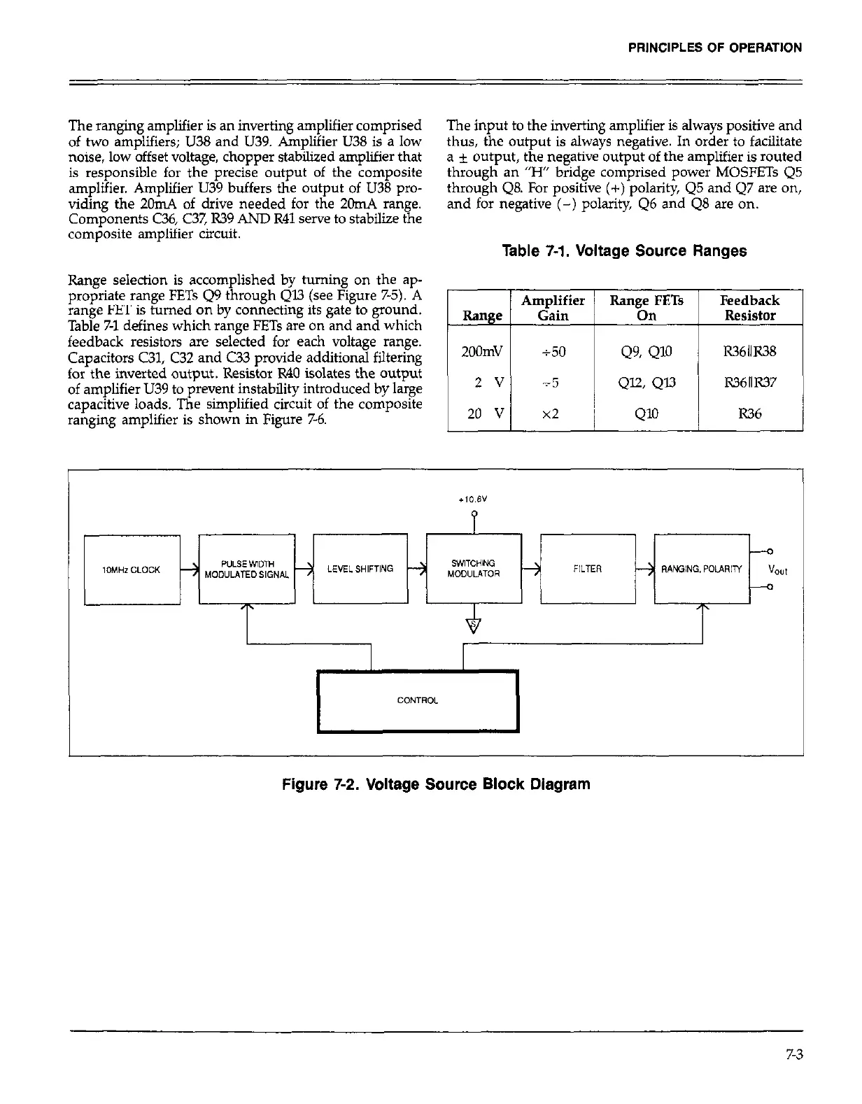
Figure 7-2. Voltage Source Block Diagram
7-3