SECTION 8
Maintenance
8.1 INTRODUCTION
This section contains information necessary to maintain,
calibrate, and troubleshoot the Model 263. Fuse replace-
ment and line voltage selection procedures are also
included.
WARNING
The procedures included in this section are for
use only by qualified service personnel. Do not
perform these procedures unless qualified to do
so. Many of the steps in this section may ex-
pose you to potentially lethal voltages that
could result in personal injury or death if nor-
mal safety precautions are not observed.
8.2 LINE VOLTAGE SELECTION
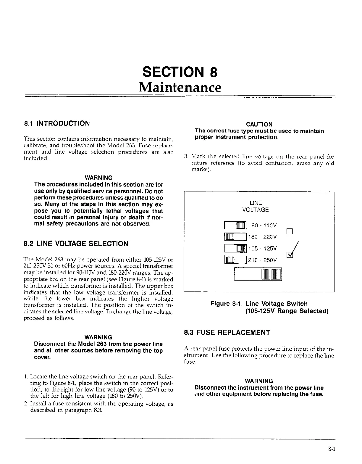
The Model 263 may be operated from either 105425V or
210-250V 50 or 60Hz power sources. A special transformer
may be installed for 90-1lOV and 180.220V ranges. The ap-
propriate box on the rear panel (see Figure 8-l) is marked
to indicate which transformer is installed. The upper box
indicates that the low voltage transformer is installed,
while the lower box indicates the higher voltage
transformer is installed. The position of the switch in-
dicates the selected line voltage. To change the line voltage,
proceed as follows.
WARNING
Disconnect the Model 263 from the power line
and all other sources before removing the top
cover.
1. Locate the line voltage switch on the rear panel. Refer-
ring to Figure 8-1, place the switch in the correct posi-
tion; to the right for low line voltage (90 to l25V) or to
the left for high line voltage (180 to 250V).
2. Install a fuse consistent with the operating voltage, as
described in paragraph 8.3.
CAUTION
The correct fuse type must be used to maintain
proper instrument protection.
3. Mark the selected line voltage on the rear panel for
future reference ito avoid confusion. erase
anv
old
r-jJjjq go-1lOV
-180.220v lx
-[105- 125V
r\210 250V
Figure 8-1. Line Voltage Switch
(105125V Range Selected)
8.3 FUSE REPLACEMENT
A rear panel fuse protects the power line input of the in-
strument. Use the following procedure to replace the line
fuse.
WARNING
Disconnect the instrument from the power line
and other equipment before replacing the fuse.
8-l