OPERATION
2. To display the alternate display mode, press any
ADJUST button. These buttons toggle the display be-
tween the two modes.
3. To enter the displayed mode, again press the MENU
button. The instrument will return to normal opera-
tion and the programmed display mode will be stored
in memory. Thus, the instrument wiIl power-up to the
programmed display mode.
3.9.3 Program tc
This program is used to check and/or change the status
of the temperature compensation feature of the Model 263.
Temperature compensation is discussed in paragraph
3.11.1. Perform the following steps to use this program:
1. Press the MENU button until the status of the
temperature compensation is displayed. If temperature
compensation is enabled, the following message will
be displayed:
tc 1
If temperature compensation is disabled, the follow-
ing message will be dislayed:
tc 0
2. To change the displayed status of temperature com-
pensation press any one of the ADJUST buttons. These
two buttons toggle the display between 1 and 0 (on and
off).
3. To enter the displayed status of temperature compen-
sation, again press the MENU button. The instrument
will return to normal operation. Unlike the other pro-
grams, programming temperature compensation for 0
(off) will not be remembered on the next power-up. On
power-up, temperature compensation will always be
enabled (1).
3.10 SOURCING TECHNIQUES
Using the front panel controls has already been discussed
in detail in previous paragraphs. Thus, this section will
not repeat the details of performing each task required to
source a particular parameter. Detailed information on
function selection, range changes, data entry, guard, and
zero can be found in paragraphs 3.4 through 3.8. The ob-
jective of this section is to show how all the operating tasks
combine to properly source each parameter.
3.10.1 Connections
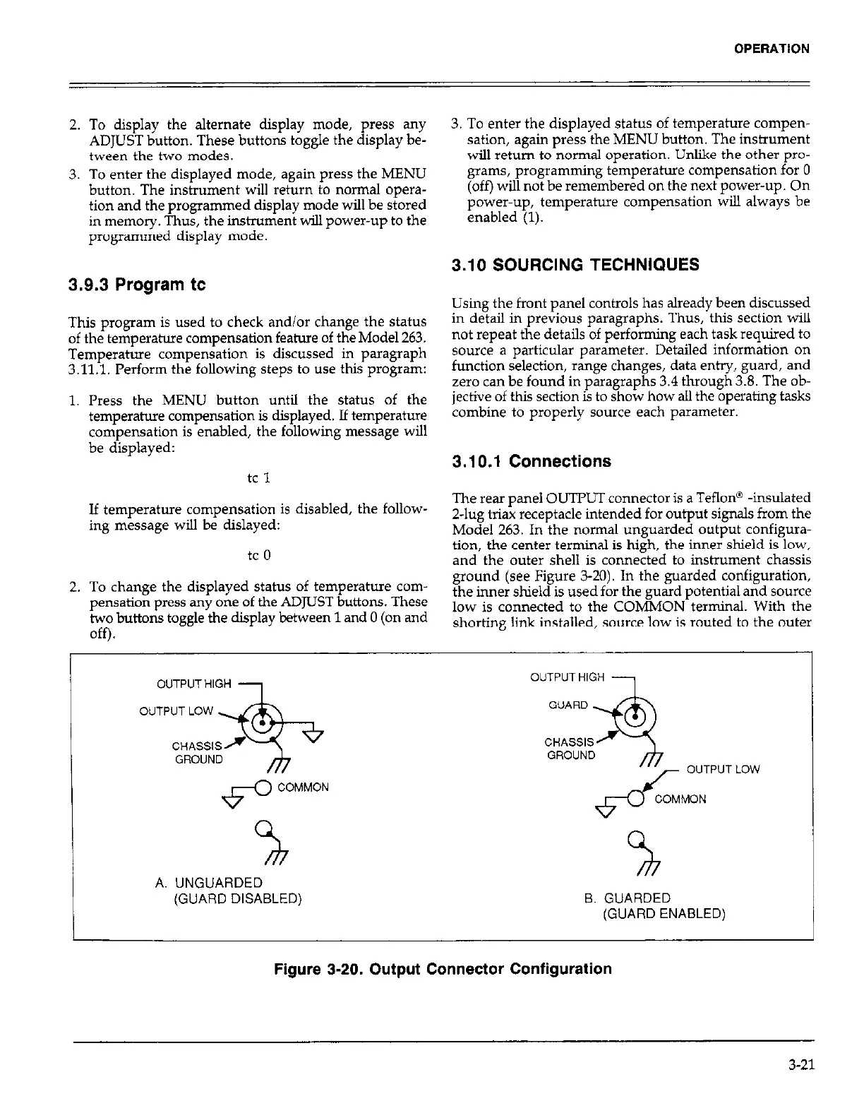
The rear panel OUTPUT connector is a Teflon@ -insulated
2-lug triax receptacle intended for output signals from the
Model 263. In the
normal
unguarded output configura-
tion, the center terminal is high, the inner shield is low,
and the outer shell is connected to instrument chassis
ground (see Figure 3-20). In the guarded configuration,
the inner shield is used for the guard potential and source
low is connected to the COMMON terminal. With the
shorting link installed, source low is routed to the outer
OUTPUTHIGH
OUTPUT HIGH
OUTPUT LOW
37-
GUARD
.
CHASSlSf
CHASSIS
GROUND
3
GROUND
OUTPUT LOW
6-O
COMMON
d
COMMON
%
x
A. UNGUARDED
(GUARD DISABLED)
B. GUARDED
(GUARD ENABLED)
I
Figure 3-20. Output Connector Configuration
3-21