APPLICATIONS
Manual Adjustments:
1. Input offset adjustment
2. Input current adjustment
3. Voltage source calibration adjustments
Digital Calibration (Front Panel or IEEE-488 Bus):
4. Amps calibration
5. Coulombs calibration
6. Volts calibration
7. Ohms calibration
The voltage source is calibrated third since this is a manual
adjustment. This allows the digital calibration procedures
to be grouped together.
In addition to the above sequence, the ranges for each
function must be calibrated in the order given. Note that
you should never calibrate a range using a suppress or
a zero correct value taken on a different range.
5.3.5 Manual Calibration Adjustments
After performing the following manual calibration ad-
justments, proceed to either front panel digital calibration
(paragraph 5.3.6) or IEEE-U Bus Digital Calibration (para-
graph 5.3.7).
A. Input Offset Adjustment
Perform the following steps to null out any small offset
in the input amplifier:
1. Disconnect all input signals from the Model 617.
2. Remove the two screws securing the top cover and
remove the cover from the instrument.
3. Select the amps function and place the instrument on
the 2pA range.
4. Enable zero check, but leave zero correct disabled.
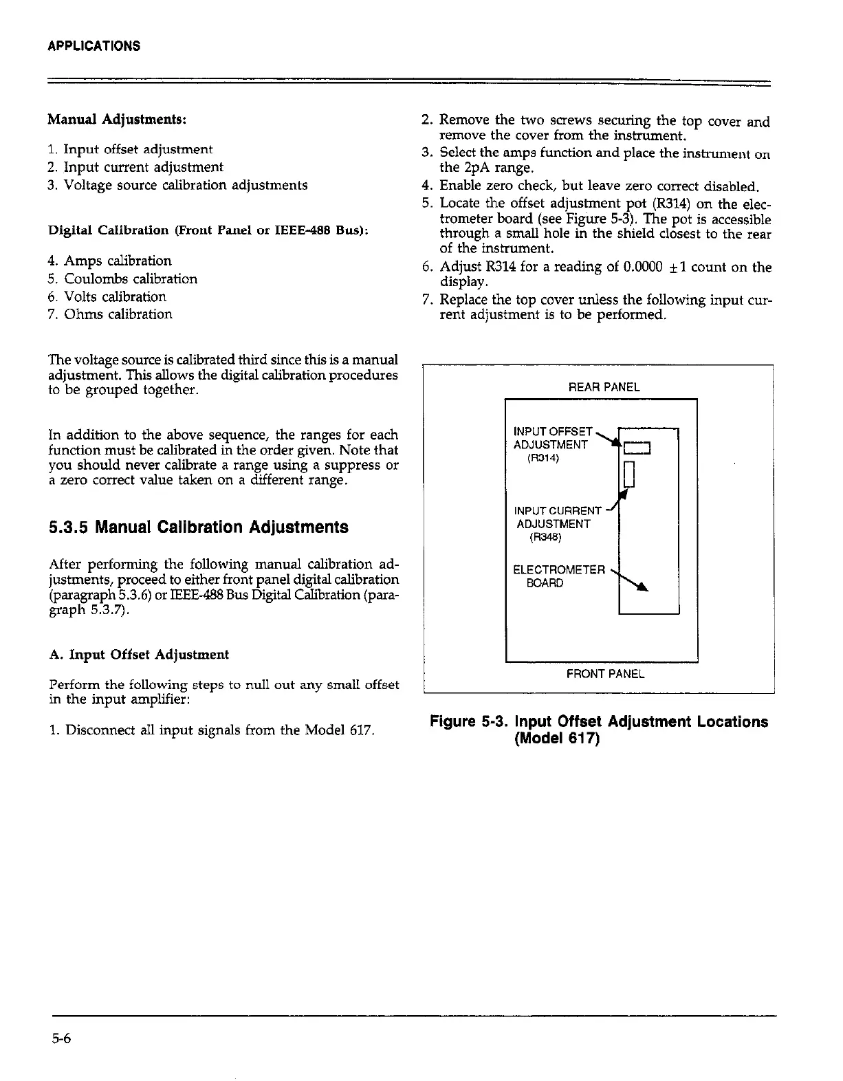
5. Locate the offset adjustment pot (R314) on the elec-
trometer board (see Figiue 53). The pot is accessible
through a small hole in the shield closest to the rear
of the instrument.
6. Adjust R314 for a reading of 0.0000 *l count on the
display.
7. Replace the top cover unless the following input cur-
rent adjustment is to be performed.
1
REAR PANEL
INPUTOFFSET
ADJUSTMENT
(R314)
INPUTCURRENT
ADJUSTMENT
mw
ELECTROMETER
BOARD
FRONT PANEL
Figure 5-3. Input Offset Adjustment Locations
(Model 617)
5-6