OPERATION
shell of the OUTPUT connector. Paragraph 3.7 explains
how to use the guarded output of the Model 263.
For equipment that does not use triax input connectors,
adapters may be needed to connect an input connector
to a female triax output connector. To mate a BNC input
connector to a triax output connector, attach a male BNC
to a female triav adapter (Keithley Model 4804) to the BNC
connector. The supplied triax cable can then be used to
make the connection. To mate a UHF input connector to
a triax output connector, attach a UHF-to-BNC adapter
(Keithley PIN CS-115) to the UHF input connector, and
attach a male BNC to female triax adapter to the BNC con-
nector. The triax cable can then be used to make the
connection.
WARNING
The maximum applied common-mode voltage
(the voltage between output low and chassis
ground) is 350V peak. Exceeding this value may
create a shock hazard and cause damage to the
instrument. If using the Model 6167 or 6191 in-
put adapter, any applied common-mode
voltage also exists between output low and Its
chassis.
3.10.2 Sourcing Ohms
Perform the following procedure to source ohms to an
electrometer. Make sure that the electrometer is set to
measure ohms and on autorange, if available. Otherwise,
change ranges as required to keep the electrometer on the
optimum range.
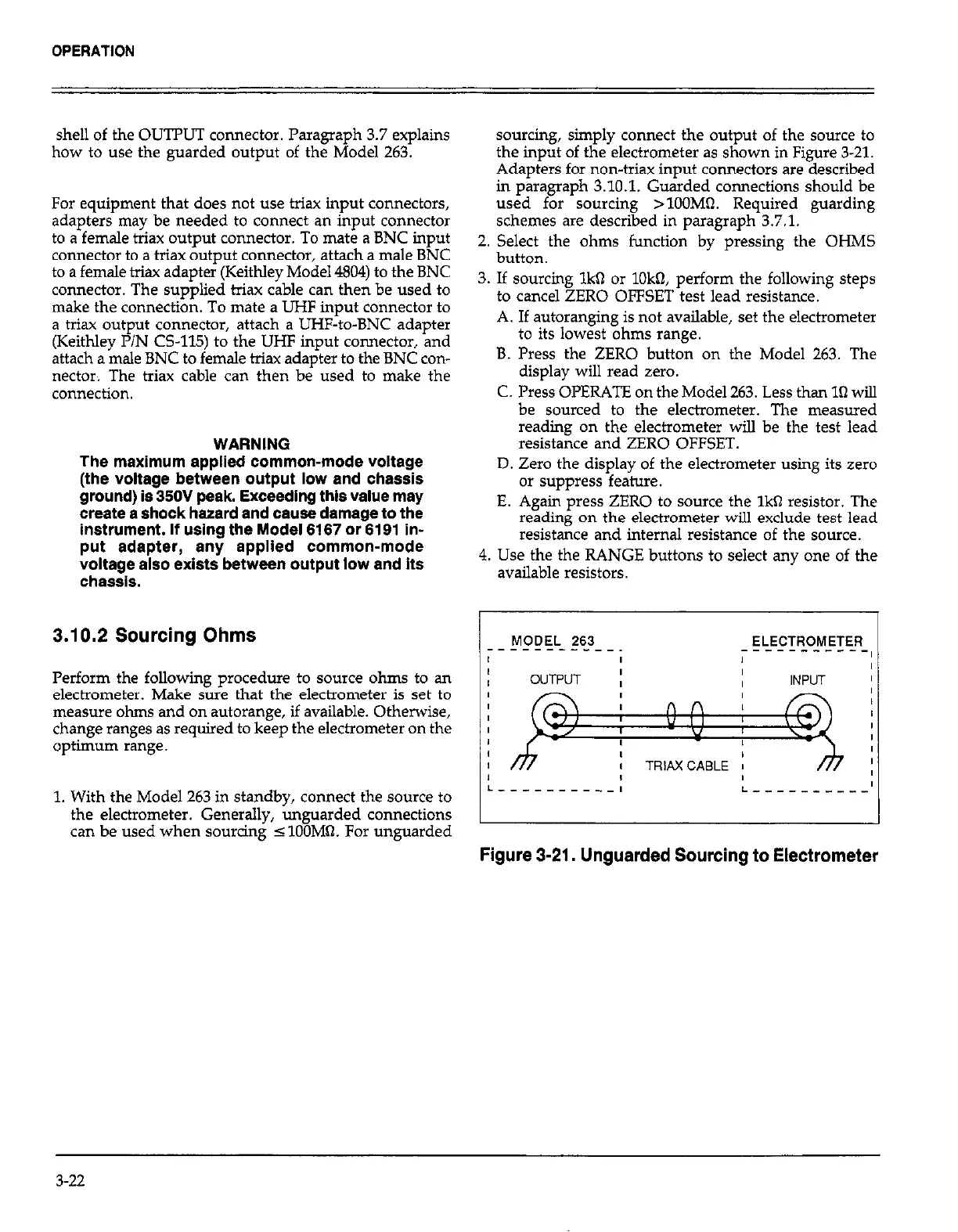
1. With the Model 263 in standby, connect the source to
the electrometer. Generally, unguarded connections
can be used when sourcing 5 lOOM% For unguarded
sourcing, simply connect the output of the source to
the input of the electrometer as shown in Figure 3-21.
Adapters for non-triax input connectors are described
in paragraph 3.10.1. Guarded connections should be
used for sourcing >lOOMO. Required guarding
schemes are described in paragraph 3.7.1.
2. Select the ohms function by pressing the OHMS
button.
3. If sourcing lkbl or lOkQ, perform the following steps
to cancel ZERO OFFSET test lead resistance.
A. If autoranging is not available, set the electrometer
to its lowest ohms range.
B. Press the ZERO button on the Model 263. The
display will read zero.
C. Press OPERATE on the Model 263. Less than la will
be sourced to the electrometer. The measured
reading on the electrometer will be the test lead
resistance and ZERO OFFSET.
D. Zero the display of the electrometer using its zero
or suppress feature.
E. Again press ZERO to source the lka resistor. The
reading on the electrometer will exclude test lead
resistance and internal resistance of the source.
4. Use the the RANGE buttons to select any one of the
available resistors.
MODEL 263 ELECTROMETER
__-__- ______
I
I
-----------I
I
I
I
OUTPUT
I I
I
I
INPUT
I
I
I
I
I
4
I
I TRIAXCABLE I
I
I
I
I
L------- ___I
L - - - - _ - - _ - -’
Figure 3-21. Unguarded Sourcing to Electrometer
3-22