MAINTENANCE
Note: When reinstalling the mother board assembly,
make sure that all the spring contact clips make con-
tact with their respective shields. There is one spring
contact clip located on the trace side of the mother
board and two clips on the rear panel.
4. The display board can now be removed as follows:
A. Remove the two screws that secure front panel
assembly to the bottom case. These screw are located
near the bottom of the display PC board.
B. Carefully slide the front panel assembly upward
(along the grooves in the sides of the bottom case)
away from the bottom case.
Note: When reinstalling the front panel assembly,
make sure the bottom edge of the display PC board
seats between the guide tabs located on the bottom
case.
C. To remove the display board, remove the two screws
securing it to the fmnt panel assembly.
Note: When reinstalling the front panel assembly,
make sure the spring contact clip is making contact
with the display board shield and and the bottom
case shield.
5. The ins!xument can be re-assembled by reversing the
above procedure. Make sure that all boards are properly
seated and secured, and that all connections are pro-
perly made. To ensure proper operation, shields must
be replaced and fastened securely.
WARNING
To ensure continued protection against safety
hazards, power line ground must be connected
to the rear panel. This connection is made by
the two kep nuts securing the AC power recep-
tacle to the rear panel. Make sure that these
nuts are securely installed before applying
power to the instrument.
8.7 TROUBLESHOOTING
The troubleshooting information contained in this section
is intended for qualified personnel having a basic under-
standing of analog and digital circuitry. The individual
should also be experienced at using typical test equipment,
as well as ordinary troubleshooting procedures. The in-
formation presented here has been written to assist in
isolating a defective circuit or circuit section. Isolation of
the specific component is left to the technician. Note that
schematic diagrams and component layout drawings,
which are an essential aid in troubleshooting, are located
at the end of Section 9.
8.7.1 Recommended Test Equipment
Success in troubleshooting complex equipment like the
Model 263 depends not only on the skill of the technician,
but also relies on the use of accurate, reliable test equip-
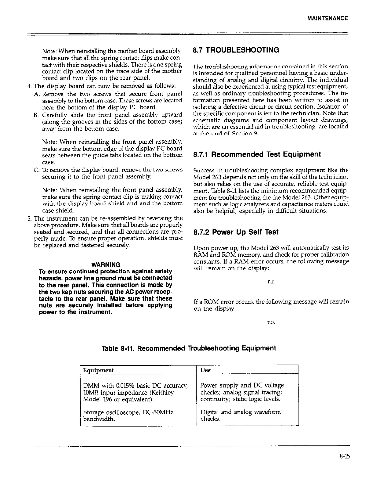
ment. Table 8-11 lists the minimum recommended equip-
ment for troubleshooting the the Model 263. Other equip-
ment such as logic analyzers and capacitance meters could
also be helpful, especially in difficult situations.
8.7.2 Power Up Self Test
Upon power up, the Model 263 will automatically test its
RAM and ROM memory, and check for proper calibration
constants. If a RAM error occurs, the following message
will remain on the display:
r.r.
If a ROM enor occurs, the following message will remain
on the display:
r.0.
Table 8-11. Recommended Troubleshooting Equipment
Equipment
Use
DMM with 0.015% basic DC accuracy,
Power supply and DC voltage
1OMfl input impedance (Keithley
checks; analog signal tracing;
Model 196 or equivalent).
continuity; static logic levels.
Storage osdlloscope, DC-50MHz
Digital and analog waveform
bandwidth.
checks.
8-15