PRINCIPLES OF OPERATION
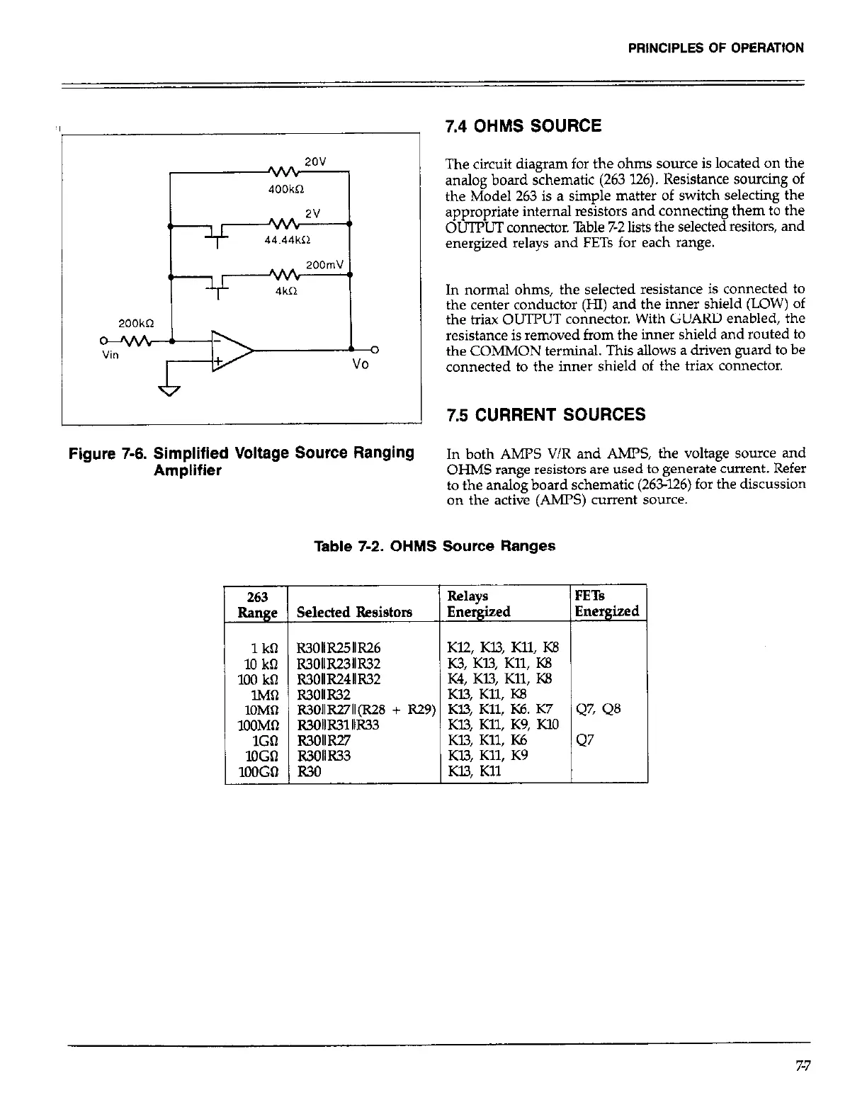
:igure 7-6. Simplified Voltage Source Ranging
Amplifier
263
Ran e
1kQ
10 ka
100 kfl
.
lMn
lOMfl
1OOMQ
1Gil
loGn
1OOGn
7.4
OHMS SOURCE
The circuit diagram for the ohm source is located on the
analog board schematic (263 126). Resistance sourcing of
the Model 263 is a simple matter of switch selecting the
appropriate internal resistors and connecting them to the
OUTPUT connector. ?Bble 7-2 lists the selected resitors, and
energized relays and FETs for each range.
In normal ohms, the selected resistance is connected to
the center conductor (HI) and the inner shield (LOW) of
the triax OUTPUT connector. With GUARD enabled, the
resistance is removed from the inner shield and routed to
the COMMON terminal. This allows a driven guard to be
connected to the inner shield of the triax connector.
7.5 CURRENT SOURCES
In both AMPS V/R and AMPS, the voltage source and
OHMS range resistors are used to generate current. Refer
to the analog board schematic (263-126) for the discussion
on the active (AMPS) current source.
Table 7-2. OHMS Source Ranges
Selected Resistors
Relays FETS
Energized Energized
R3011R2511R26
Kl2, K13, Kll, K8
R3OllR23llR32
K3, Kl3, Kll, KB
R3OllR24llR32
K4, Kl3, Kll, KS
R3OllR32 Kl.3, Kll, KE
R3OllR27ll(R28 + R29) K13, Kll, K6. K7
47, Q8
R3alR31llR33
Kl3, Kll, KS, KlO
l?3011Fc7
KB, Kll, K6
Q7
R3OllR33
Kl3, Kll, K9
R.30
Kl3. Kll
-I
7-7