PRINCIPLES OF OPERATION
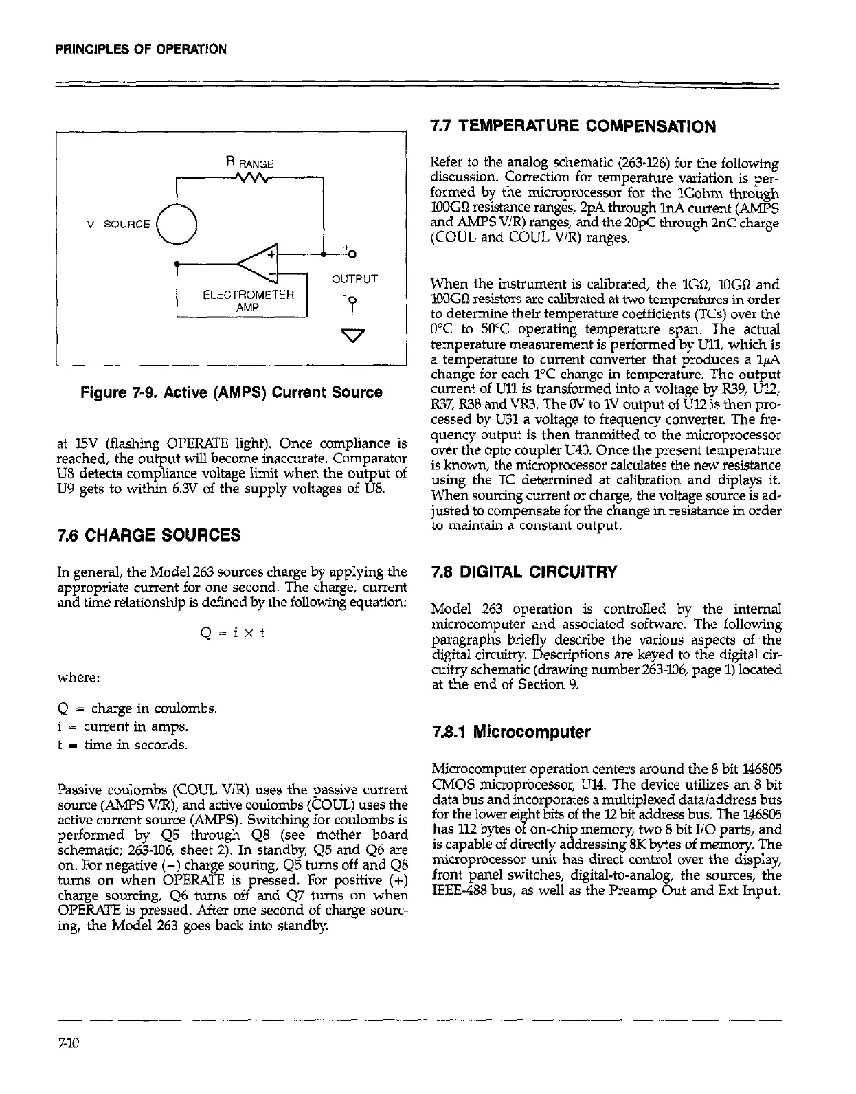
V SOURCE
ELECTROMETER
Figure 7-9. Active (AMPS) Current Source
at l5V (flashing OPERATE light). Once compliance is
reached, the output will become inaccurate. Comparator
US detects compliance voltage limit when the output of
LJ9 gets to within 6.3V of the supply voltages of LJ8.
7.6 CHARGE SOURCES
In general, the Model 263 sources charge by applying the
appropriate current for one second. The charge, current
and time relationship is defined by the following equation:
Q=ixt
where:
Q = charge in coulombs.
i = current in amps.
t = time in seconds.
Passive coulombs (COUL VIR) uses the passive current
source (AMPS V/R), and active coulombs (COUL) uses the
active current source (AMPS). Switching for coulombs is
performed by Q5 through QS (see mother board
schematic; 263-106, sheet 2). In standby, Q5 and Q6 are
on. For negative (-) char e souring, Q5 turns off and Q8
turns on when OPERA& is pressed. For positive (+)
charge sourcing, Q6 turns off and Q7 turns on when
OPERATE is pressed. After one second of charge sourc-
ing, the Model 263 goes back into standby.
7.7 TEMPERATURE COMPENSATION
Refer to the analog schematic (263-126) for the following
discussion. Correction for temperature variation is per-
formed by the microprocessor for the 1Gohm through
lOOGO resistance ranges, 2pA through lnA current (AMPS
and AMPS V/R) ranges, and the 2OpC through 2nC charge
(COUL and COUL V/R) ranges.
When the instrument is calibrated, the lG0, 1OGSZ and
lOOGQ resistors are calibrated at two temperatures in order
to determine their temperature coefficients (TCs) over the
OT to 50°C operating temperature span. The actual
temperature measurement is performed by LJll, which is
a temperature to current converter that produces a 14
change for each PC change in temperature. The output
current of Ull is transformed into a voltage by R39, Ul2,
RY, R38 and VR3. The OV to 1V output of Ul2 is then pro-
cessed by U31 a voltage to frequency converter. The fre-
quency output is then tram&ted to the microprocessor
over the opto coupler U43. Once the present temperature
is known, the microprocessor calculates the new resistance
using the ‘IC determined at calibration and diplays it.
When sourcing current or charge, the voltage source is ad-
justed to compensate for the change in resistance in order
to maintain a constant output.
7.6 DIGITAL CIRCUITRY
Model 263 operation is controlled by the internal
microcomputer and associated software. The following
paragraphs briefly describe the various aspects of ?he
digital circuitry. Descriptions are keyed to the digital cir-
cuitry schematic (drawing number263-106, page 1) located
at the end of Section 9.
7.8.1 Microcomputer
Microcomputer operation centers around the 8 bit 146805
CMOS microprocessor, U14. The device utilizes an 8 bit
data bus and incorporates a multiplexed data/address bus
for the lower eight bits of the 12 bit address bus. The 146805
has 112 bytes of on-chip memory, two 8 bit I/O parts, and
is capable of directly addressing 8K bytes of memory. The
microprocessor unit has direct control over the display,
front panel switches, digital-to-analog, the sources, the
IEEE-488 bus, as well as the Prearnp Out and Ext Input.
7-10