Notes:
1. With the instrument in Operate, use the ZERO button
to source zero ohms. This button toggles the output
between zero and the selected output resistor.
2. In STANDBY, the lOOGO resistor is sourced.
3. To achieve rated accuracy, do not apply more than 20V
across the lk0 through lOG0 resistors, or 1OOV across
the lOOGo resistor.
4. Additional specifications for OHMS are contained in
Table 3-3.
Resistor Temperature Coefficient-The resistor tempera-
ture coefficient (TC) given in the OHMS specifications are
the corrected TCs of the resistors. That is, the TCs with
the Temperature Compensation feature enabled. With
Temperature Compensation enabled, the Model 263 up-
dates the display to correspond to the actual resistor value.
The Model 263 does not change or correct the actual value
of the resistor, it only reports the value at a given tempera-
ture. The temperature coefficient of the GO resistors with
Temperature Compensation disabled, (no correction) is as
follows:
lOOGo: 800 ppmi”C
1OGQ: 170 ppm/“C
1GQ: 170 ppmi”C
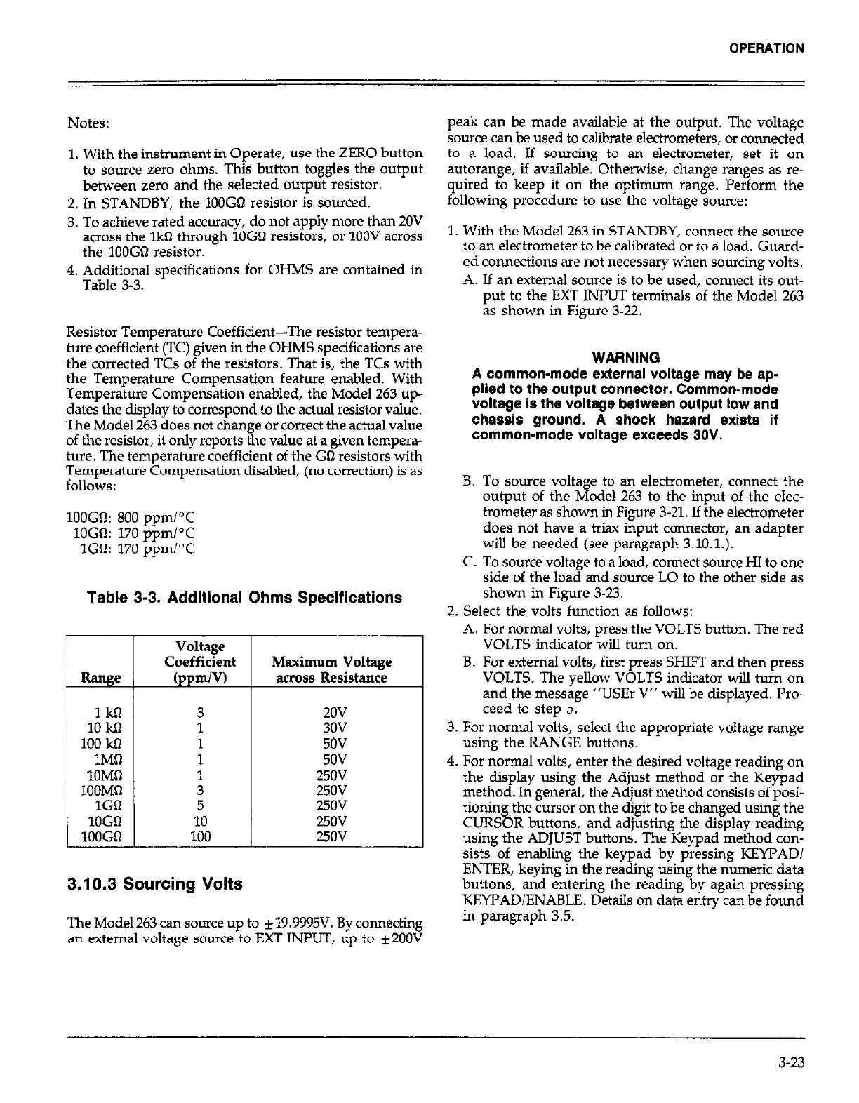
Table 3-3. Additional Ohms Specifications
Range
1
kil
10
kfi
100
k0
1Mll
10Mil
1OOMfl
1GO
lOGil
lOOGO
Voltage
Coefficient
(ppm/V)
3
1
1
1
I
3
5
10
100
Maximum Voltage
across Resistance
2ov
3ov
5ov
5ov
250V
250v
25ov
250v
250v
3.10.3 Sourcing Volts
The Model 263 can source up to + 19.9995V. By connecting
an external voltage source to EXT INPUT, up to i2OOV
peak can be made available at the output. The voltage
source can be used to calibrate electrometers, or connected
to a load. If sourcing to an electrometer, set it on
autorange, if available. Otherwise, change ranges as re-
quired to keep it on the optimum range. Perform the
following procedure to use the voltage source:
1. With the Model 263 in STANDBY, connect the source
to an electrometer to be calibrated or to a load. Guard-
ed connections are not necessary when sourcing volts.
A. If an external source is to be used, connect its out-
put to the EXT INPUT terminals of the Model 263
as shown in
Figure 3-22.
WARNING
A common-mode external voltage may be ap-
plied to the output connector. Common-mode
voltage is the voltage between output low and
chassis ground. A shock hazard exists if
common-mode voltage exceeds 30V.
B. To source voltage to an electrometer, connect the
output of the Model 263 to the input of the elec-
trometer as shown in Figure 3-21. If the electrometer
does not have a triax input connector, an adapter
will be needed (see paragraph 3.10.1.).
C. To source voltage to a load, connect source HI to one
side of the load and source LO to the other side as
shown in Figure 3-23.
2. Select the volts function as follows:
A. For normal volts, press the VOLTS button. The red
VOLTS indicator will turn on.
B. For external volts, fist press SHIFT and then press
VOLTS. The yellow VOLTS indicator will turn on
and the message “USEr V” will be displayed. Pro-
ceed to step 5.
3. For normal volts, select the appropriate voltage range
using the RANGE buttons.
4. For normal volts, enter the desired voltage reading on
the display using the Adjust method or the Keypad
method. In general, the Adjust method consists of posi-
tioning the cursor on the digit to be changed using the
CURSOR buttons, and adjusting the display reading
using the ADJUST buttons. The Keypad method con-
sists of enabling the keypad by pressing KEYFAD/
ENTER, keying in the reading using the numeric data
buttons, and entering the reading by again pressing
KEYT’ADIENABLE. Details on data entry can be found
in paragraph 3.5.
3-23