APPENDIX F
DATA BUS
DATA BYTE
TRANSFER
CONTROL
GENERAL
INTERFACE
MANAGEMENI
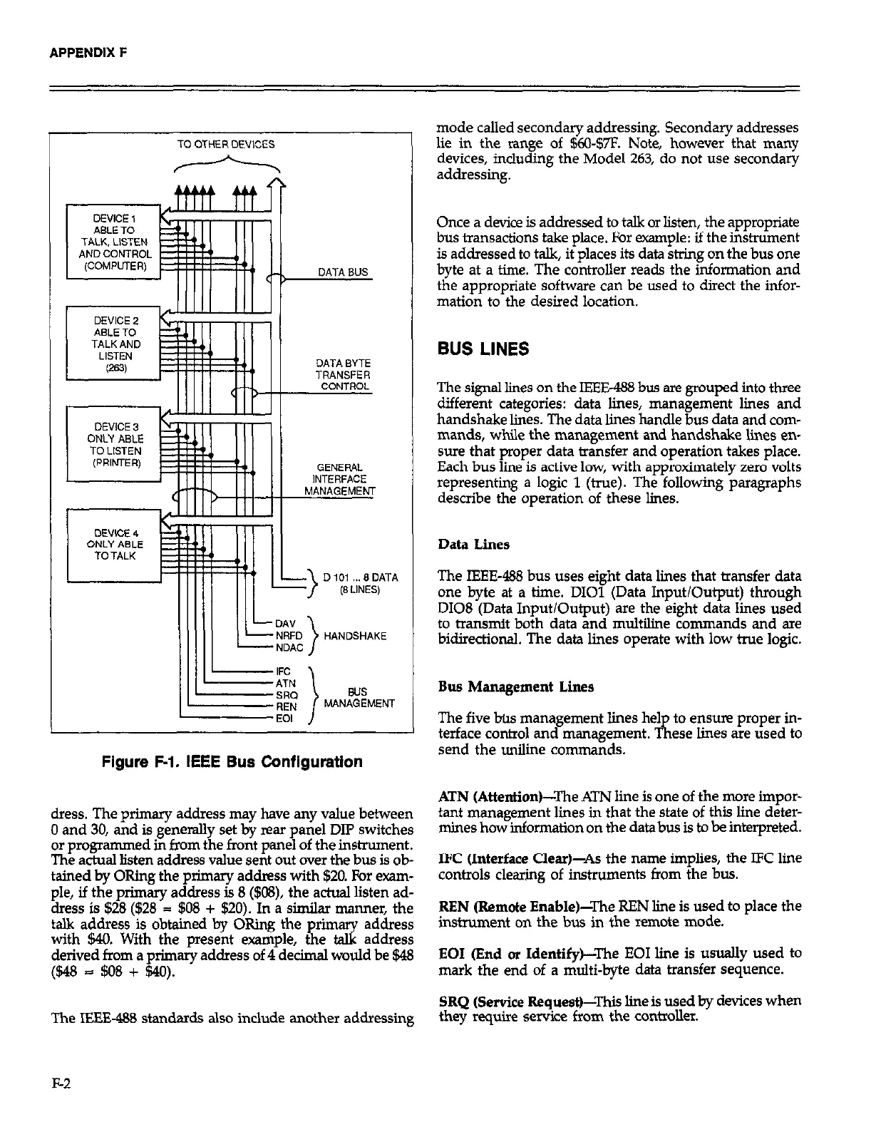
Figure F-1. IEEE Bus Configuration
dress. The primary address may have any value between
0 and 30, and is generally set by rear
anel DIP switches
or programmed in from the front pane
Y of the inshxment.
The actual listen address value sent out over the bus is ob-
tained by ORing the pximary addrass with $20. For exam-
ple, if the primary address is 8 ($C@), the achul listen ad-
dress is $28 ($26 = $08 + $20). In a similar manner, the
talk address is obtained by ORing the prim
tz
address
with $40. With the present example, the
address
derived from a primary address of 4 decimal would be $48
($48 = $08 + $40).
The IEEE-488 standards also include another addressing
mode called secondary addressing. Secondary addresses
lie in the range of $Kl-$7F. Note, however that many
devices, including the Model 263, do not use secondary
addressing.
Once a device is addressed to talk or listen, the appropriate
bus transactions take place. For example: if the instrument
is addressed to talk, it places its data stdng on the bus one
byte at a time. The controller reads the information and
the appropriate software can be used to direct the infor-
mation to the desired location.
BUS LINES
The signal lines on the IEEE& bus are grouped into three
different categories: data lines, management limes and
handshake lines. The data lines handle bus data and com-
mands, while the management and handshake lines en-
sure that proper data transfer and operation takes place.
Each bus line is active low, with approximately zero volts
representing a logic 1 (true). The following paragraphs
describe the operation of these lines.
Data Lines
The IEEE-488 bus uses eight data lines that transfer data
one byte at a time. DIOl (Data Input/Output) through
D108 (Data Input/Output) are the eight data lines used
to transmit both data and multiline commands and are
bidirectional. The data lines operate with low true logic.
Bus Management Lines
The five bt~ management lines he1
to ensme proper in-
terface control and management. &ese lines are used to
send the uniline commands.
ATN (Attention)-The ATN line is one of the more impor-
tant management lines in that the state of this line deter-
mines how information on the databus is to be interpreted.
IFC (Interface Clear)-As the name implies, the IFC line
controls clearing of instruments from the bus.
REN (Remote Enable)-The REN line is used to place the
instrument
on
the bus in the remote mode.
EOI (End or Identify)-The EOI line is usually used to
mark the end of a multi-byte data transfer sequence.
SRQ (Service Request)-This line is used by devices when
they require service from the controller.
F-2