OPERATION
MODEL 263
---------------------------------------
I
R, =lkRto 1OOGR
I
dvv
I
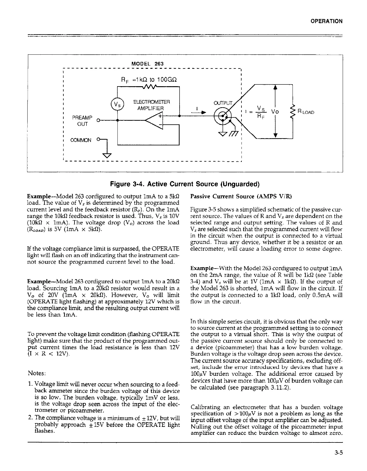
Figure 3-4. Active Current Source (Unguarded)
Passive Current Source (AMPS V/R)
Example-Model 263 configured to output 1mA to a 5kQ
load. The value of V, is determined by the programmed
current level and the feedback resistor (R,). On the 1mA
range the 1Okn feedback resistor is used. Thus, V, is 1OV
(10kQ x ImA). The voltage drop (V,) across the load
(RLOAO) is 5V (1mA x 5kR).
Figure 3-5 shows a simplified schematic of the passive cur-
rent source. The values of R and V, are dependent on the
selected range and output setting. The values of R and
V, we selected such that the programmed current will flow
in the circuit when the output is connected to a virtual
ground. Thus any device, whether it be a resistor or an
electrometer, will cause a loading error to some degree.
If the voltage compliance limit is surpassed, the OPERATE
light will flash on an off indicating that the instrument cm-
not source the programmed current level to the load.
Example-Model 263 configured to output 1mA to a 20kR
load. Sourcing lm.4 to a 20kO resistor would result in a
V, of 20V (1mA x 20kQ However, V0 will limit
(OPERATE light flashing) at approximately 12V which is
the compliance limit, and the resulting output current wiIl
be less than ImA.
To prevent the voltage limit condition (flashing OPERATE
light) make sure that the product of the programmed out-
put current times the load resistance is less than 12V
(I x R < 12V).
Notes:
1. Voltage limit will never occur when sourcing to a feed-
back ammeter since the burden voltage of this device
is so low. The burden voltage, typically 1mV or less,
is the voltage drop seen across the input of the elec-
trometer
or picoammeter.
2. The compliance voltage is a minimum of * 12V, but will
probably approach *15V before the OPERATE light
flashes.
Example-With the Model 263 configured to output 1mA
on the 2mA range, the value of R will be 1kR (see Table
3-4) and V, will be at 1V (ImA x 1kR). If the output of
the Model 263 is shorted, ImA will flow in the circuit. If
the output is connected to a 1kQ load, only 0.5mA will
flow in the circuit.
In this simple series circuit, it is obvious that the only way
to sowce current at the programmed setting is to connect
the output to a virtual short. This is why the output of
the passive current source should only be connected to
a device (picoammeter) that has a low burden voltage.
Burden voltage is the voltage drop seen across the device.
The current source accuracy specifications, excluding off-
set, include the error introduced by devices that have a
1OOpV burden voltage. The additional error caused by
devices that have more than 1OOpV of burden voltage can
be calculated (see paragraph 3.11.2).
Calibrating an electrometer that has a burden voltage
specification of > 1OOpV is not a problem as long as the
input offset voltage of the input amplifier can be adjusted.
Nulling out the offset voltage of the picoammeter input
amplifier can reduce the burden voltage to almost zero.
3-5