OPERATION
this situation guarding will be required (see paragraph
3.7.2).
2. Select the amps or coulombs function as follows:
A. Select an amps function as follows:
a. For AMPS, press the AMPS button. The red
AMPS light will turn on.
b. For AMPS V/R, first press SHIFT then AMPS.
The red and yellow indicator lights will turn on.
B. Select coulombs function as follows:
a. For COUL, press COUL. The red COUL indicator
will turn on.
b. For COUL V/R, fist press SHIFT then COLJL.
The red and yellow indicators will turn on.
3. Select the desired range using the RANGE buttons.
4. Enter the desired current reading on the display using
the Adjust method or the Keypad method. In general,
the Adjust method consists of positioning the cursor
on the digit to be changed using the CURSOR buttons
and adjusting the display reading using the ADJUST
buttons. The Keypad method consists of enabling the
keypad by pressing KEYPAD/ENTER, keying in the
reading using the numeric data buttons, and entering
the reading by again pressing KEYPAD/ENTER. Details
on data entry can be found in paragraph 3.5.
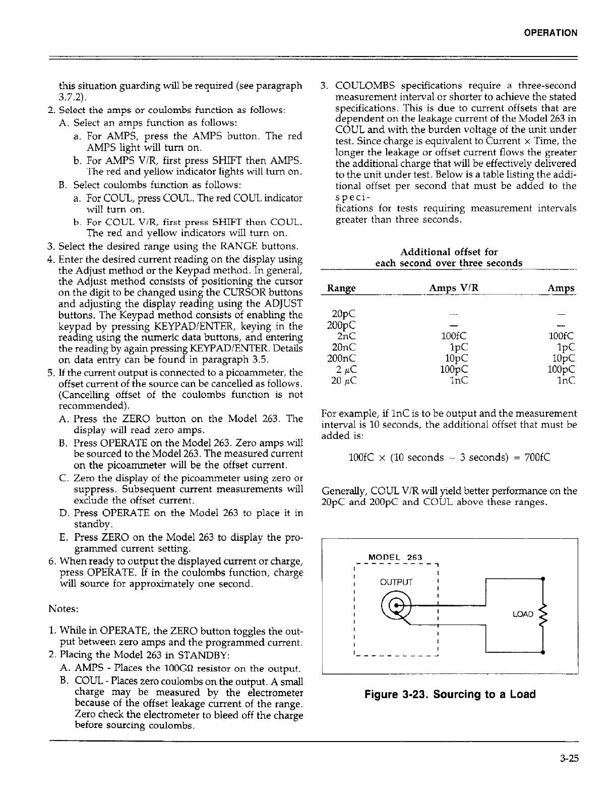
5. If the current output is connected to a pica-eter, the
offset current of the source can be cancelled as follows.
(Cancelling offset of the coulombs function is not
recommended).
A. Press the ZERO button on the Model 263. The
display will read zero amps.
B. Press OPERATE on the Model 263. Zero amps will
be sourced to the Model 263. The measured current
on the picoammeter will be the offset current.
C. Zero the display of the picoammeter using zero or
suppress. Subsequent current measurements will
exclude the offset current.
D. Press OPERATE on the Model 263 to place it in
standby.
E. Press ZERO on the Model 263 to display the pro-
grammed current setting.
6. When ready to output the displayed current or charge,
press OPERATE. If in the coulombs function, charge
will source for approximately one second.
Notes:
1. While in OPERATE, the ZERO button toggles the out-
put between zero amps and the programmed current.
2. Placing the Model 263 in STANDBY:
A. AMPS - Places the 100GQ resistor on the output.
B. COUL Places zero coulombs on the output. A small
charge may be measured by the electrometer
because of the offset leakage current of the range.
Zero check the electrometer to bleed off the charge
before sourcing coulombs.
3. COULOMBS specifications require a three-second
measurement interval or shorter to achieve the stated
specifications. This is due to current offsets that are
dependent on the leakage current of the Model 263 in
COUL and with the burden voltage of the unit under
test. Since charge is equivalent to Current x Time, the
longer the leakage or offset current flows the greater
the additional charge that will be effectively delivered
to the unit under test. Below is a table listing the addi-
tional offset per second that must be added to the
speci-
fications for tests requiring measurement intervals
greater than three seconds.
Additional offset for
each second over three seconds
Range
2opc
2oopc
2nC
Amps V/R Amps
- -
- -
100fC 100fC
20nC
200nC
2
PC
20 UC
IPC
1opc
1oopc
1nC
1PC
1opc
1oopc
1nC
For example, if 1nC is to be output and the measurement
interval is 10 seconds, the additional offset that must be
added is:
1OOfC x (10 seconds - 3 seconds) = 700fC
Generally, COUL V/R will yield better performance on the
2OpC and 2OOpC and COUL above these ranges.
/
MODEL 263
----------7
I___
I
Figure 3-23. Sourcing to a Load
3-25