IEEE-488 PROGRAMMING
1 = SRQ BY 263
(SERIAL POLL BYTE 0
1= CHARGE WNE
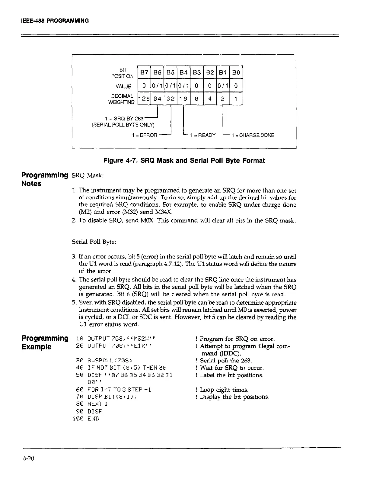
Figure 4-7. SRQ Mask and Serial Poll Byte Format
Programming
SRQ Mask:
. .
Notes
1. The instrument may be programmed to generate an SRQ for more than one set
of conditions simultaneously. To do so, simply add up the decimal bit values for
the required SRQ conditions. For example, to enable SRQ under charge done
(MZ) and error (M32) send MNX.
2. To disable SRQ, send MOX. This command will clear all bits in the SRQ mask.
Serial Poll Byte:
3. If an error occurs, bit 5 (error) in the serial poll byte will latch and remain so until
the Ul word is read (paragraph 4.7.12). The Ul status word will define the nature
of the error.
4. The serial poll byte should be read to clear the SRQ line once the instrument has
generated an SRQ. All bits in the serial poll byte will be latched when the SRQ
is generated. Bit 6 (SRQ) will be cleared when the serial poll byte is read.
5. Even with SRQ disabled, the serial poll byte can b@ read to determine appropriate
instrument conditions. All set bits will remain latched until MO is asserted, power
is cycled, or a DCL or SDC is sent. However, bit 5 can be cleared by reading the
Ul error status word.
! Program for SRQ on error.
! Attempt to program illegal com-
mand (IDDC).
! Serial poll the 263.
! Wait for SRQ to occur.
! Label the bit positions.
! Loop eight times.
! Display the bit positions
4-20