As shown above, there are five register sets associated with System Event Status. These registers
summarize system status for various nodes connected to the TSP-Link. Note that all nodes on the
TSP-Link share a copy of the system summary registers once the TSP-Link has been initialized. This
feature allows all nodes to access the status models of other nodes, including SRQ.
In a TSP-Link system, the status model can be configured such that a status event in any node in the
system can set the RQS (Request for Service) bit of the Master Node Status Byte. See TSP-Link
system status (on page C-20) for details on using the status model in a TSP-Link system.
Attributes are summarized in status.system.* (on page 11-393), status.system2.* (on page 11-395),
status.system3.* (on page 11-398), status.system4.* (on page 11-400), and status.system5.* (on
page 11-402).
For example, any of the following commands will set the EXT enable bit:
status.system.enable = status.system.EXT
status.system.enable = status.system.EXTENSION_BIT
status.system.enable = 1
When reading a register, a numeric value is returned. The binary equivalent of this value indicates
which bits in the register are set. For details, see Reading registers (on page C-15). For example, the
following command will read the system enable register:
print(status.system.enable)
The bits used in the system register sets are described as follows:
• Bit B0, Extension Bit (EXT): Set bit indicates that an extension bit from another system status
register is set.
• Bits B1-B14* NODEN: Indicates a bit on TSP-Link node n has been set (N = 1 to 64).
• Bits B15: Not used.
*status.system5 does not use bits B9 through B15.
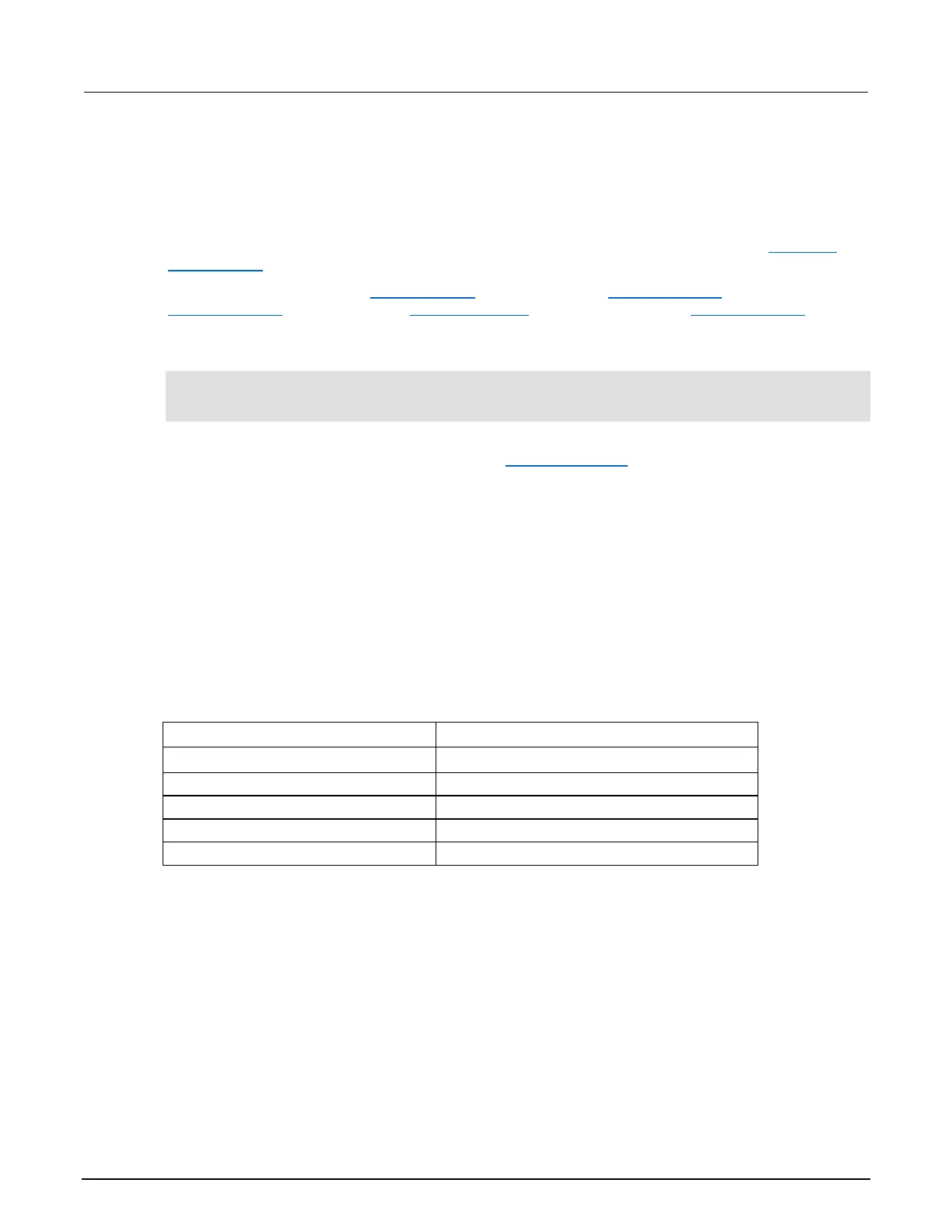
Refer to the following table for available N values:

 Loading...


