EasyManuals Logo

Keithley 3706A Reference Manual

Keithley 3706A
936 pages
To Next Page IconTo Next Page
To Previous Page IconTo Previous Page
Page #253 background imageLoading...
Page #253 background image
Section 8: Theory of operation Series 3700A System Switch/Multimeter Reference Manual
8-2 3700AS-901-01 Rev. D/June 2018
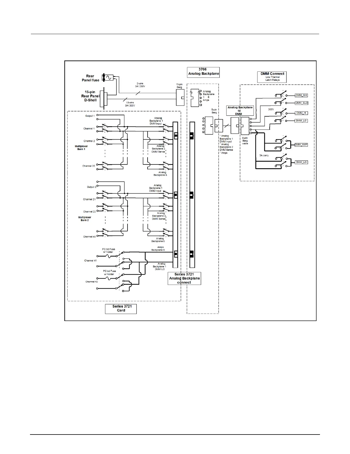
Figure 101: Rear panel to backplane to DMM connect relays schematic
Line cycle synchronization
Synchronizing A/D conversions with the frequency of the power line increases common mode and
normal mode noise rejection. When line cycle synchronization is enabled, the measurement is
initiated at the first positive-going zero crossing of the power line cycle after the trigger.
The following figure shows a measurement process that consists of two A/D conversions. If the
trigger occurs during the positive cycle of the power line (Trigger #1), the A/D conversion starts with
the positive-going zero crossing of the power line cycle. If the next trigger (Trigger #2) occurs during
the negative cycle, then the measurement process also starts with the positive-going zero crossing.

Table of Contents

Other manuals for Keithley 3706A

Questions and Answers:

Question and Answer IconNeed help?

Do you have a question about the Keithley 3706A and is the answer not in the manual?

Keithley 3706A Specifications

General IconGeneral
Model3706A
CategorySystem Switch/Multimeter
Voltage Range100 nV to 300 V
Basic DC Voltage Accuracy0.0035%
Basic Resistance Accuracy0.01%
Maximum Channels576
Maximum Voltage300 V
ConnectivityLAN, USB, GPIB
InterfaceLAN, USB, GPIB
Switching MatrixYes
Channels576 (6-slot mainframe)
Maximum Current3 A

Related product manuals