Model 6487 Reference Manual Limit Tests and Digital I/O 8-13
`^rqflk Do not exceed +33V maximum voltage on pin 5 of the digital I/O port
and do not use any output line to sink >500mA. Exceeding these limits
may cause damage to the instrument that is not covered by the
warranty.
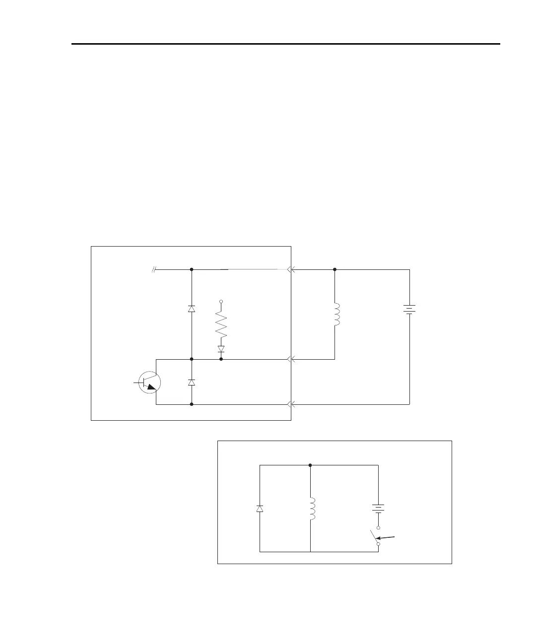
An externally powered relay connected to the digital output port is shown in Figure 8-10.
Other externally powered devices can be similarly connected by replacing the relay with
the device. When the output line is set LO (0V), the output transistor sinks current through
the external device. In the HI state, the output transistor is off (transistor switch open).
This interrupts current flow through the external device.
Figure 8-10
Controlling externally powered relays
+5V
1kΩ
Pull Up
Resistor
Pin 9 - Digital Ground
Pin 1 - Digital Output #1
Pin 5 - External Voltage Flyback Connection
Digital Output #1
Flyback Diode
To three other
digital outputs
Relay
Coil
(+)
(+)
(-)
(-)
External Power
(+5V to +33V)
Transistor
Switch
Flyback
Diode
Equivalent Circuit
Relay
Coil
External Power
(+5V to +33V)
Model 6487

 Loading...


