Rev. A
HW 10/25/02
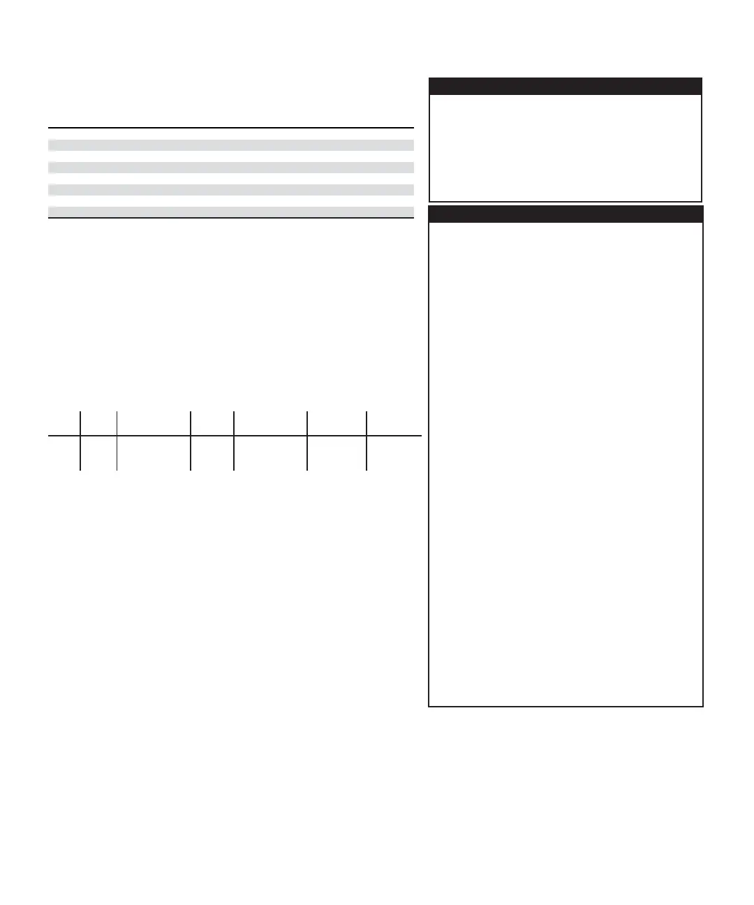
6487 Picoammeter Specifications
TYPICAL ANALOG
5¹⁄₂ DIGIT ACCURACY (1YR)
1
RISE TIME (10% TO 90%)
3
DEFAULT ±(% RDG. + OFFSET) TYPICAL DAMPING
4
RANGE RESOLUTION 18°–28°C, 0–70% RH RMS NOISE
2
OFF ON
2 nA 10 fA 0.3 % + 400 fA 20 fA 4 ms 80 ms
20 nA 100 fA 0.2 % + 1 pA 20 fA 4 ms 80 ms
200 nA 1 pA 0.15 % + 10 pA 1 pA 300 µs 1 ms
2 µA 10 pA 0.15% + 100 pA 1 pA 300 µs 1 ms
20 µA 100 pA 0.1 % + 1 nA 100 pA 110 µs 110 µs
200 µA 1 nA 0.1 % + 10 nA 100 pA 110 µs 110 µs
2 mA 10 nA 0.1 % + 100 nA 10 nA 110 µs 110 µs
20 mA 100 nA 0.1 % + 1 µA 10 nA 110 µs 110 µs
Specifications are subject to change without notice.
REMOTE OPERATION
IEEE-488 BUS IMPLEMENTATION: SCPI (IEEE-488.2, SCPI-1996.0);
DDC (IEEE-488.1).
LANGUAGE EMULATION: Keithley Model 486/487 emulation via
DDC mode.
RS-232 IMPLEMENTATION:
Supports: SCPI 1996.0.
Baud Rates: 300, 600, 1200, 2400, 4800, 9600, 19.2k, 38.4k, 57.6k.
Protocols: Xon/Xoff, 7 or 8 bit ASCII, parity-odd/even/none.
Connector: DB-9 TXD/RXD/GND.
GENERAL
AMMETER INPUT CONNECTOR: Three lug triaxial on rear panel.
ANALOG OUTPUT CONNECTOR: Two banana jacks on rear panel.
VOLTAGE SOURCE OUTPUT CONNECTOR: Two banana jacks on rear
panel.
INTERLOCK CONNECTOR: 4 pin DIN.
TRIGGER LINE: Available, see manual for usage.
DISPLAY: 12 character vacuum fluorescent.
DIGITAL FILTER: Median and averaging (selectable from 2 to 100
readings).
RANGING: Automatic or manual.
AUTORANGING TIME
3
: <250ms (analog filter off, 1PLC)
OVERRANGE INDICATION: Display reads “OVRFLOW”.
CONVERSION TIME: Selectable 0.01 PLC to 60 PLC (50PLC under
50Hz operation). (Adjustable from 200µs to 1s)
READING RATE:
To internal buffer 1000 readings/second
1
To IEEE-488 bus 900 readings/second
1, 2
BUFFER: Stores up to 3000 readings.
PROGRAMS: Provide front panel access to IEEE address, choice of
engineering units or scientific notation, and digital calibration.
EMC: Conforms with European Union Directive 89/336/EEC,
EN61326-1.
SAFETY: Conforms with European Union Directive 73/23/EEC,
EN61010-1, CAT I.
ENVIRONMENT:
Operating: 0°–50°C; relative humidity 70% non-condensing, up to
35°C. Above 35°C, derate humidity by 3% for each °C.
Storage: –10°C to +65°C.
WARM-UP: 1 hour to rated accuracy (see manual for recommended
procedure).
POWER: 100–120V or 220–240V, 50–60Hz, (50VA).
PHYSICAL:
Case Dimensions: 90mm high × 214mm wide × 369mm deep (3
1
⁄
2
in.
× 8
3
⁄
8
in. × 14
9
⁄
16
in.).
Working Dimensions: From front of case to rear including power
cord and IEEE-488 connector: 394mm (15.5 inches).
NET WEIGHT: <4.7 kg (<10.3 lbs).
Notes:
1
0.01 PLC, digital filters off, front panel off, auto zero off.
2
Binary transfer mode.
IEEE-488.1.
3
Measured from trigger in to meter complete
.
TEMPERATURE COEFFICIENT: 0°–18°C & 28°–50°C. For each °C, add 0.1 × (% rdg + offset) to
accuracy spec.
INPUT VOLTAGE BURDEN: <200µV on all ranges except <1mV on 20mA range.
MAXIMUM INPUT CAPACITANCE: Stable to 10nF on all nA ranges and 2µA range; 1µF on 20µA
and 200µA ranges, and on mA ranges.
MAXIMUM CONTINUOUS INPUT VOLTAGE: 505 VDC
NMRR
1
: (50 or 60Hz) :60dB
ISOLATION (Ammeter Common or Voltage Source to chassis): Typically >1×10
11
Ω in parallel
with <1nF.
MAXIMUM COMMON MODE VOLTAGE (Between Chassis and Voltage Source or Ammeter):
505 VDC.
MAXIMUM VOLTAGE BETWEEN VOLTAGE SOURCE AND AMMETER: 505 VDC
ANALOG OUTPUT: Scaled voltage output (inverting 2V full scale on all ranges) 2.5% ±2mV
ANALOG OUTPUT IMPEDANCE
3
: <100Ω, DC-2kHz.
VOLTAGE SOURCE
Range Step Size Accuracy
5
Noise (p-p) Temperature Typical Rise Typical Fall
(Max)
(typical)
±
(% PROG. + OFFSET)
0.1 - 10 Hz Coefficient Time
6,8
Time
7,8
18°C
- 28°C, 0 - 70% R.H. (10%-90%) (90%-10%)
±10.100 200µV 0.1% + 1mV <50µV (0.005% + 20µV) / ˚C 250
µs 150 µs
±50.500 1mV 0.1% + 4mV <150µV (0.005% + 200µV) / ˚C 250
µs 300 µs
±505.00 10mV 0.15% + 40mV <1.5mV (0.008% + 2mV ) / ˚C 4.5 ms 1 ms
SELECTABLE CURRENT LIMIT: 2.5mA, 250
µ
A, 25
µ
A for 50V and 500V ranges, 25mA additional
limit for 10V range. All current limits are -20%/+35% of nominal.
WIDEBAND NOISE
9
: <30mVp-p 0.1Hz - 20MHz.
TYPICAL TIME STABILITY:
±
(0.003% + 1mV) over 24 hours at constant temperature (within 1°C,
between 18°C - 28°C, after 5 minute settling).
OUTPUT RESISTANCE: <2.5Ω.
VOLTAGE SWEEPS: Supports linear voltage sweeps on fixed source range, one current or resist-
ance measurement per step. Maximum sweep rate: 200 steps per second. Maximum step count
3000. Optional delay between step and measure.
RESISTANCE MEASUREMENT (V/I): Used with voltage source; resistance calculated from voltage
setting and measured current. Accuracy is based on voltage source accuracy plus ammeter
accuracy. Typical accuracy better than 0.6% for readings between 1kΩ and 1TΩ.
ALTERNATING VOLTAGE RESISTANCE MEASUREMENT: Offers alternating voltage resistance
measurements for resistances from 10
9
Ω to 10
15
Ω. Alternates between 0V and user-selectable
voltage up to
±505V.
1
At 1 PLC – limited to 60 rdgs/sec under this condition.
2
At 6 PLC, 1 standard deviation, 100 readings, filter off, capped input – limited to 10 rdgs/sec
under this condition.
3
Measured at analog output with resistive load >2kΩ.
4
Maximum rise time can be up to 25% greater.
5
Accuracy does not include output resistance/load regulation.
6
Rise Time is from 0V to
± full-scale voltage (increasing magnitude)
.
7
Fall Time is from
± full-scale voltage to 0V (decreasing magnitude)
.
8
For capacitive loads, add C*ΔV/I
Limit
to Rise Time, and C*ΔV/1mA to Fall Time.
9
Measured with LO connected to chassis ground.

 Loading...


