Model 6487 Reference Manual Applications Guide G-11
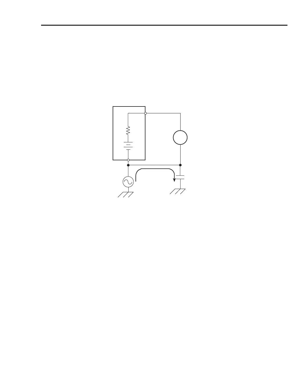
As shown in Figure G-8, this will cause a current (i) to flow through the low to ground
capacitance of the picoammeter (A). Picoammeter HI is connected to the higher resistance
side of the circuit being measured, the “R” side of this current source. This circuit is con-
nected properly, so this current does not flow through the picoammeter and, therefore,
does not cause any measurement errors.
Figure G-8
Proper connection
However, when the HI of the picoammeter is connected to the low impedance side of the
DUT, this AC current (i) flows through the picoammeter (A) as illustrated in Figure G-9.
This current may affect the measurement accuracy, especially at low signal levels.
Current Source
6487
Picoammeter
+
-
i
HI
LO
R
A

 Loading...


