Model 6487 Reference Manual Measurement Concepts and Connections 2-15
The 2V analog output signal is not corrected during calibration. Gain errors of up to 2.5%
may appear at this output, depending on range.
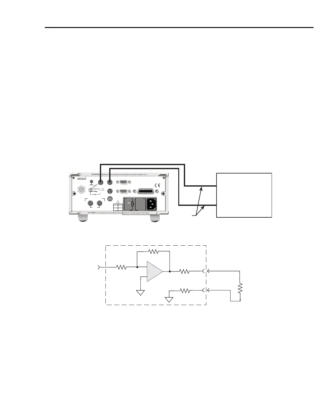
The output impedance is <100¾. To minimize the effects of loading, the input impedance
of the device connected to the ANALOG OUT should be as high as possible. For example,
for a device that has an input impedance of 1M¾, the error due to loading will be approxi-
mately 0.01%. High capacitance connected to the analog output will increase the rise time.
An internal 1k¾ resistance is connected between COM and analog common for protec-
tion. The effects of this resistance on analog output accuracy are negligible.
Rel and the result of mX+b, m/X+b, or LOG have no affect on the analog output. The 2V
analog output is scaled only to the actual input.
Figure 2-11
Typical analog output connections
Test Lead
120
LINE RATING
50, 60Hz
50 VA MAX
INPUT
(CHANGE IEEE ADDRESS
WITH FRONT PANEL MENU)
IEEE-488
CAT I
TRIGGER LINK
RS-232
MADE IN
U.S .A .
ANALOG OUT
DIGITAL I/O
INTERLOCK
505V
MAX
V-SOURCE OUTPUT
505V PK TO CHASSIS
LO HI
!
!
FUSE LINE
400mAT
(SB)
100 VAC
120 VAC
200mAT
(SB)
220 VAC
240 VAC
505V PK
505V PK
505V PK
* 1kΩ included for protection.
Virtually 0Ω for accuracy purposes.
Model 6487 Rear Panel
R
L
= Input Resistance of
measuring device
Input from
Prescaler
COM
A
+
-
A
<100Ω
Measuring Device
(i.e. Chart recorder)
Analog Output
A. Connections
LO
HI
B. Equivalent Circuit
Model 6487
1kΩ∗