Product Manuals/Man-1096M_SyncroAS Marine 16 Page 10 of 38
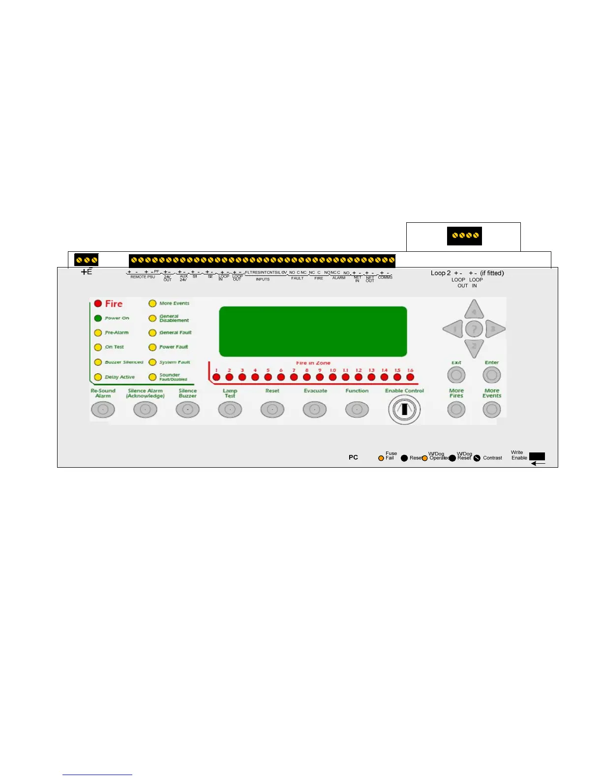
7. Front panel controls
The front panel contains controls for operating and programming the panel.
The lamp test and silence buzzer buttons can be operated at any time. (Access level 1)
The More Fires and More Events buttons can be operated at any time when there are more events than can be displayed on the
screen. (Access level 1).
The menu navigation buttons (1, 2, 3 and 4) can be used to enter the password to Access level 2 (2222) which then enables the
Silence Alarm (Acknowledge), Re-sound Alarm, Reset, Evacuate and Function buttons. This also gives the user access to the Access
level 2 menu facilities such as disabling and testing parts of the system.
Access level 2 can also be entered by operation of the Enable control keyswitch on models that have this switch fitted.
The internal panel buzzer will “beep” whenever a button is pressed.
The Help (?) button offers additional information relating to the current status of the control panel. For example, if the panel is in an
alarm or fault condition then advice on the recommended action will be displayed when the ? button is pressed or if a menu function
is being accessed then help relating to that function will be displayed when the ? button is pressed.
With the lid of the control open, more controls are revealed. These controls are strictly for service personnel and should not be
operated by the user under any circumstances. Opening the front cover also gives access to the PC connection port for
programming.
If the processor stops running or re-boots for any reason, the watchdog indicator (W/Dog Operated) will illuminate as a record of
this event. This indicator can only be reset by operating the watchdog reset switch (W/Dog Reset).
It is necessary under some circumstances (after a firmware upgrade for instance) to re-start the processors in the panel. A reset
switch is provided for this purpose labelled Reset.
A display contrast adjust control is provided which can be adjusted to suit the lighting conditions or position of the installed panel.
This is a rotary control and can be adjusted with a small terminal screwdriver.
In order to change the configuration of the control panel, the configuration memory must be enabled. This is done by switching the
Write Enable slide switch from its normal, right hand position, to the left as indicated by the arrow beneath it.
A warning is displayed on the LCD when the write enable switch is in the enabled position to prevent it from being inadvertently
being left in this position. This warning can be reset after the switch has been returned to its normal position by pressing the front
panel Reset button. If not reset the warning will time out a short while after the Write Enable switch is returned to the right hand
position.
All of the access level 3 controls are recessed to avoid accidental operation but all can be accessed using a small, terminal
screwdriver or similar tool.