Product Manuals/Man-1096M_SyncroAS Marine 16 Page 17 of 38
PRE-ALARM
FAULT
As can be seen from the above, a loop sounder which is sounding a TECH ALARM will change its tone in the event of EVACUATE,
FIRE or ALERT events if it is programmed to respond to all of these.
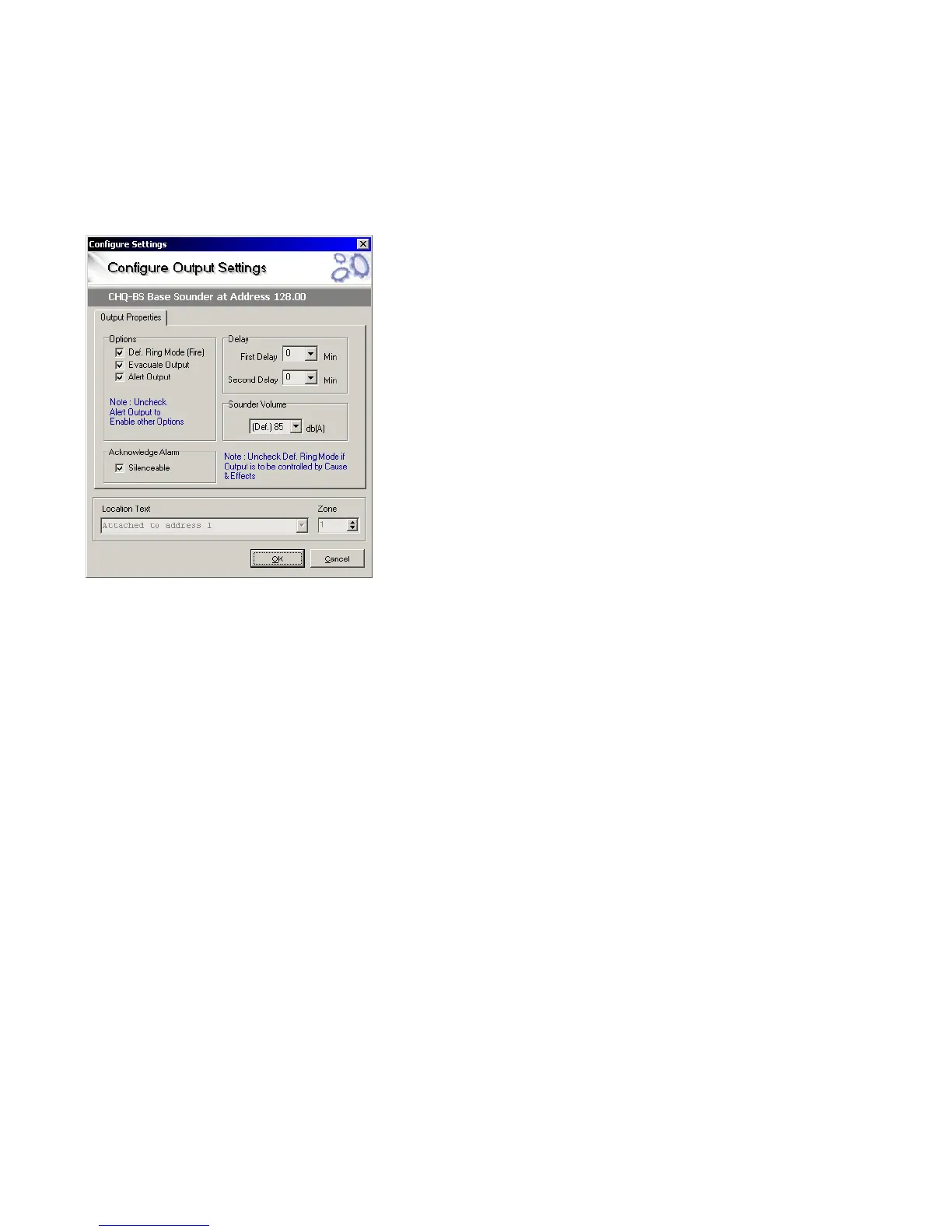
Loop sounders can be programmed to operate upon any of the event types using the configure settings window as shown below.
This window also allows the volume of the sounder to be changed from the default value, stage 1 and stage 2 delays to be set and
the sounder to be selected Silenceable or not as required.
NOTE: If a loop sounder is controlled by a cause and effect operation, then the
Tech Alarm tone will be used when the sounder is energised.
The possibility to change tones allows the fire alarm infrastructure to be utilised
to a much greater extent for other types of audible signalling than simple pulsing
or steady sounder systems.
For class change applications as an example, different tones could be used to
signal class change and break times. This could also apply to the factory
environment to signal break and shift changes.
The ability to operate individual sounders from dedicated inputs also allows the
system to be used for fire door monitoring such that the sounder nearest the
door can emit an alternative tone if the door is opened in a non-emergency
situation.
12. Panel Sounder circuits
Two conventional sounder circuits are provided in the panel, each fused at 1.0A.
A 10K end of line resistor monitors the circuits for open and short circuit faults.
Both circuits are configured to activate upon any fire condition and to de-activate when the Silence Alarm/ Acknowledge button is
pressed on the front panel or a silence input is operated. Each sounder circuit can be configured independently via the PC
configuration programme or the front panel pushbuttons (at Access level 3).
This allows sounder circuits to be operated by different methods such as zonal alarm or via cause and effects.
12.1 Stage one and stage two delays
The sounder circuits can have a single or two-stage delay if required. The first stage of delay allows up to 5 minutes for the alarm to
be acknowledged.
If the alarm is not acknowledged before the first stage delay expires, then the sounders will operate.
If the alarm is acknowledged during the first stage delay, the second stage delay (again up to 5 minutes) will start.
If the alarm is acknowledged during the first stage delay and the second stage delay is zero then the sounders will not operate.
If the Alarm is acknowledged during the second stage delay, the second stage delay (up to 5 minutes) will start and the sounders
will operate at the end of the delay unless the panel is reset.
Activation of two or more devices producing a fire action, a call point or an input configured to override output delays, will override
the delays and operate the sounders immediately.
13. Sounder controllers
Sounder controllers are available in the Hochiki, Argus Vega and Apollo ranges of devices and can be used for controlling
conventional sounders from the detection loop.
The wiring to the conventional sounder circuits is monitored for open or short circuit faults by fitting an end of line monitoring
device.
The sounder controller outputs are fully programmable as described in section 11 and section 19.
Sounder controllers require an additional 24V DC supply to power the conventional sounder circuits (or other equipment). This power
supply is also monitored for failure by the control panel.