Product Manuals/Man-1096M_SyncroAS Marine 16 Page 8 of 38
5. Cabling
It is advisable to fit cable glands and cables before re-fitting the outer cover and plate/circuit board assembly.
Cables should be brought into the cabinet using the knockouts provided and where necessary, using couplers to maximise the space
within the enclosure. Use the knockouts closest to the terminating position for each cable, to ensure cable length within the
enclosure is kept to a minimum.
Ensure that only the numbers of knockouts are removed to meet the cable termination requirements, as any additional apertures in
the enclosure will compromise the IP30 ingress protection requirements required by EN54-2.
Brass inlet bushings or cable glands should be used to maintain insulation and to ensure EMC compliance to the requirements of
EN54-2.
The screen or drain wires should be bonded to earth via metal cable glands.
The maximum size of cable, which can be terminated, is 2.5
2
mm.
The communications protocols are highly immune to noise but sensible segregation from known noise generating sources such as
mains cables is recommended.
Detection circuit cable size and type is dependant on the number and type of devices used and should be calculated for each
installation. Cable length calculators are available for both Hochiki ESP and Apollo protocols.
Cabling for sounder circuits should be sized according to sounder load and cable length but 1.5mm
2
should suffice in the majority of
cases.
The control panel requires a 230V AC supply, which should be derived from a separate fused spur, labelled “Fire Alarm - Do Not
Switch Off”.
The mains supply must include an earth conductor connected to the fixed installation earthing system of the building.
This equipment relies on the building installation for protection and requires a 5-amp protection device. The mains supply should
use cable with a minimum cross section of 1.5mm
2
.
5.1 Cable Termination
Drain wires need to be terminated at the brass cable gland to ensure EMC compliance to the requirements of EN54-2.
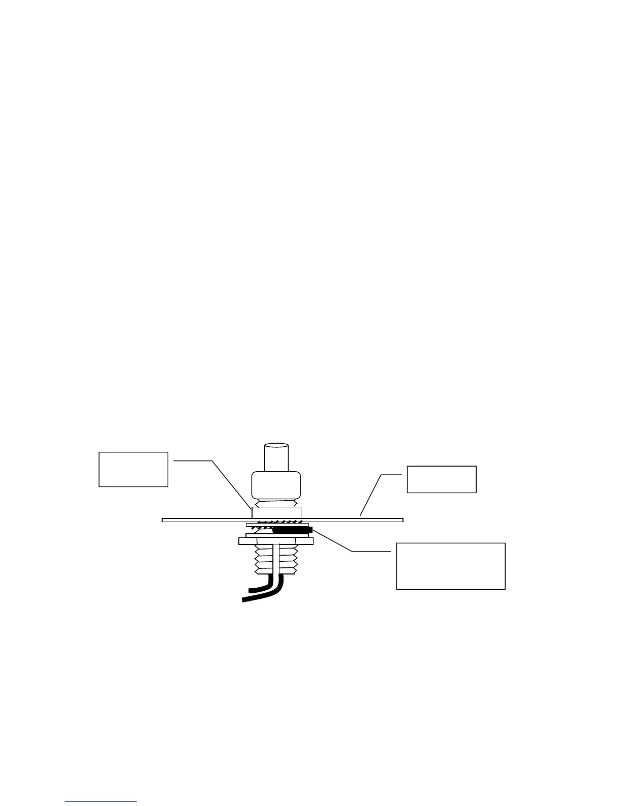
To ensure good earth bonding at entry to the panel enclosure, it is recommended that the cable drain wires are terminated using
Pirelli AXT brass cable glands. These glands have a slotted fixing thread, which allows the drain wire to be clamped between the
gland fixing nut and panel enclosure. To ensure that a good earth bonding between the drain wire and panel case, a 20mm
shakeproof washer should be used, as shown in the termination diagram below.
Drain wire clamped
between 20mm shakeproof
washer and flat washer,
held in place with fixing nut.
Pirelli AXT
Type brass
cable gland
Panel
enclosure