Product Manuals/Man-1096M_SyncroAS Marine 16 Page 15 of 38
Detection loops should be wired in a screened, fireproof cable (such as FP200) and terminated at the panel using brass cable glands.
Detection loops should have the drain wire terminated at the cable gland, as described in Section 4.1
10.1 Fitting additional detection circuit (loop card)
If an additional detection circuit (loop card) is to be fitted to a single loop Syncro ASM, it must be of the same protocol (Hochiki ESP, Apollo or
Argus Vega) as the existing detection circuit.
To fit the loop card, the control panel must have mains and battery power removed.
The metal chassis should then be removed by removing the two fixing screws that hold it in place.
The loop card is supplied in a static dissipative bag and should remain in this bag until it is to be fitted.
As with all electronic components, this circuit board is very sensitive and can be easily damaged by electrostatic discharge.
Where possible, a static protective wrist strap should be worn when handling circuit boards. Where this is not available; it is advisable to touch
a surface that is known to be connected to the earth of the fixed installation.
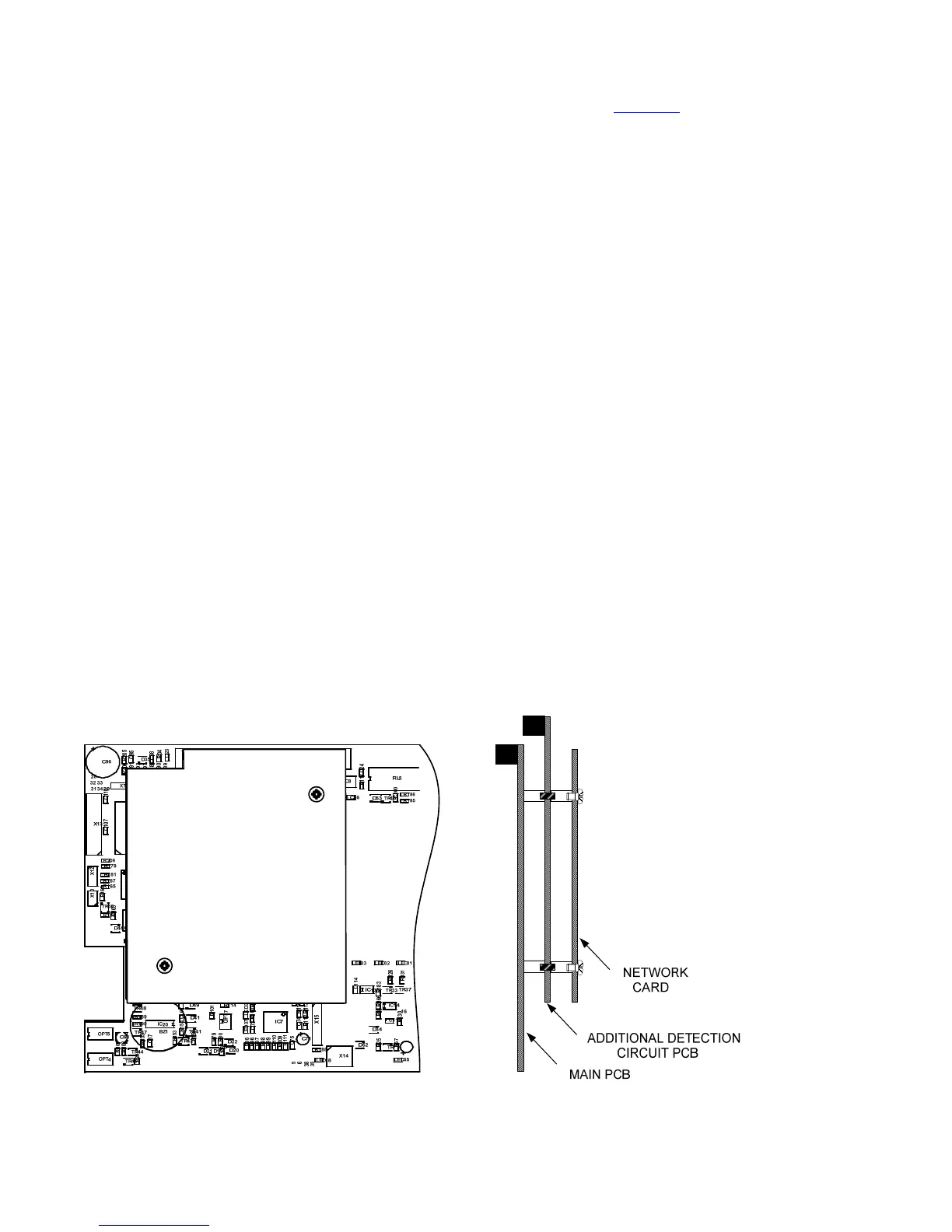
The additional loop card mounts on the left hand side of the main board and fits into two connectors labelled X7 and X8.
There are two mounting pillars on the main board to which the additional loop board should be fitted using the M3 screws and fibre
washers supplied.
If the Syncro ASM panel is part of a network, there will be a network card fitted in the position where the additional loop card will fit. The
network card must be removed by removing the two screws that hold it into position and easing it out of connectors X7 and X8 and the
additional loop card fitted in its place and secured with the two screws that are supplied with it.
The network card should now be fitted onto the connectors on the loop card and secured into place on the two pillars with the original screws
that held it in place.
After checking that the loop card is firmly located and making good contact with its connectors, the metal chassis can be screwed
back into place in the enclosure.
Unused detection circuits must have the "LOOP + OUT" to "LOOP + IN" and "LOOP - OUT" to "LOOP - IN" terminals wired together to
prevent open circuit faults from being reported.
The devices on the new detection loop should be added to the original configuration file using the Loop Explorer configuration
programme and downloaded to the panel as described in section 7.3. If this is not done the panel will report unexpected devices on
loop 2.
CAUTION – If an Autolearn is done to detect the devices on the additional loop, any previous configuration such as location text
that had been allocated to the existing devices on the original loop will be erased. For this reason, it is preferable to update the
control panel configuration via a PC.