Product Manuals/Man-1096M_SyncroAS Marine 16 Page 14 of 38
9. Facilities Menus
A number of facilities are provided which can only be reached at access level 2 or 3.
Access level 2 can be reached by entering the correct password (a 4 digit number) and pressing the enter button (or by the optional
Enable Controls key switch if fitted).
Access level 3 can only be reached from access level 2 and only by entering the correct, 4-digit password then pressing the enter
button.
Panels that have not been configured, or have been configured using the Auto Learn option, have 2222 as the default password for
Access level 2 and 3333 as the default password for Access level 3.
Passwords can only be changed using the Loop Explorer PC configuration programme.
The Access level 2 password is required by the end user, to Silence/Acknowledge, Resound Alarms, Evacuate, operate the Function
button and to Reset the system.
Any persons responsible for safety and who have been trained and authorised to use the fire alarm system should be made aware of
the Access Level 2 password (or given the enable controls key where applicable).
Without the Access Level 2 password or the enable controls key where applicable, it is not be possible to control the
fire panel so it is most important that the responsible person knows the password or is in possession of the enable key.
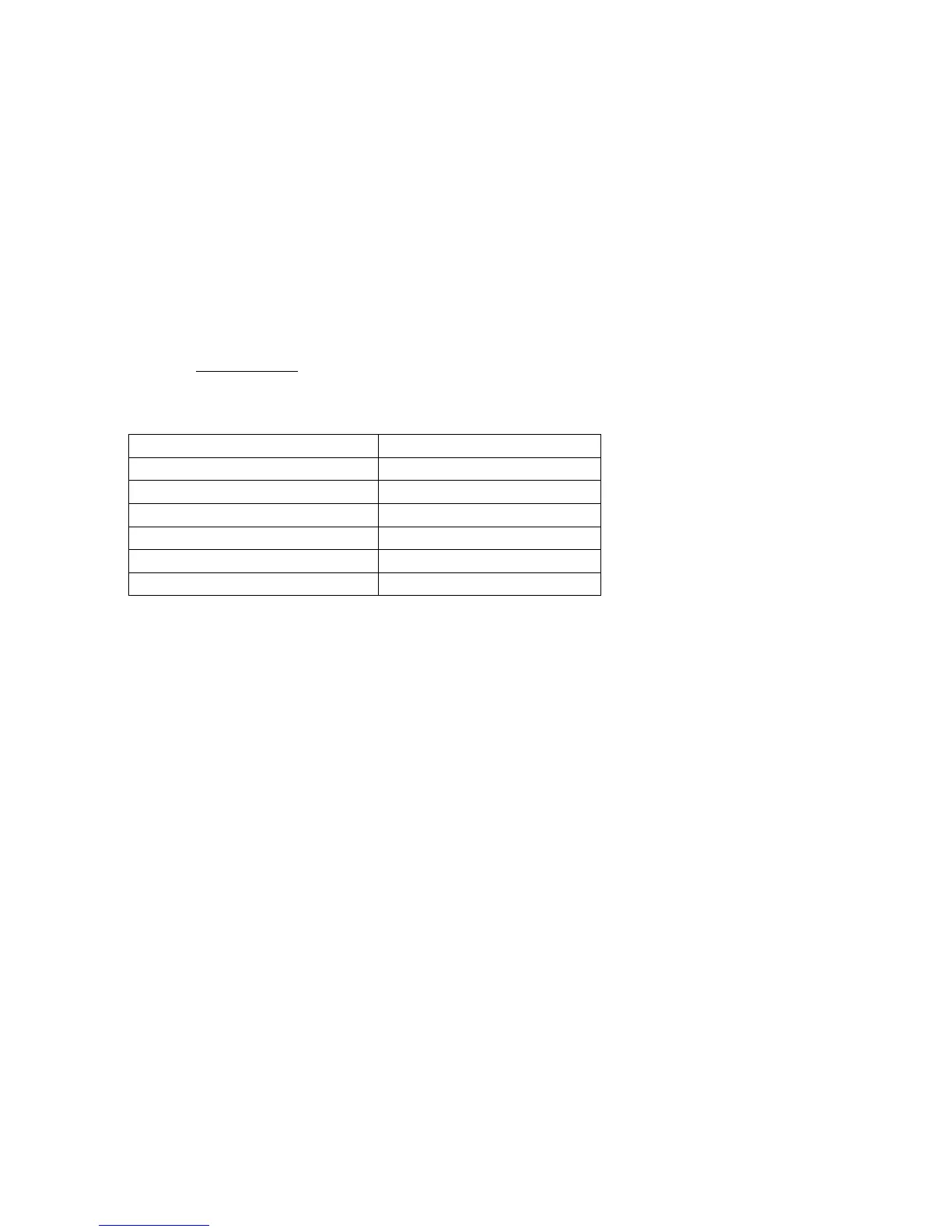
Main menu items available at access levels 2 and 3 are as follows:
ACCESS LEVEL 2 (2222) ACCESS LEVEL 3 (3333)
Disablements Edit configuration
View devices Set times
Test Zones View/print event log
Set system time Print configuration
Contamination Status Engineering Disablements and settings
Access level 3 Loop Data Test
Access level 3 enables a much higher level of control and must be restricted to persons trained and authorised to reconfigure the
site-specific data and to maintain the Syncro ASM fire panel. Typically, engineers of the fire systems company will be responsible for
Access Level 3 functions.
Before any changes are made to the configuration memory, using either the Edit Configuration or Set Times menu
options, it will be necessary to CAREFULLY set the memory write enable switch to the left hand “Enabled” position,
using a small screwdriver, or similar tool.
10. Detection circuits
Syncro ASM control panels are configured to communicate using Hochiki, Apollo or Argus Vega protocol.
Short circuit isolators must be fitted in the loop wiring such that a single short or interruption in the circuit will not prevent the
indication of a fire alarm from more than 32 detectors and/or manual call points. Argus Vega devices have built in short circuit
isolators so no additional isolators need to be fitted when using these devices.
Power is driven from the “LOOP OUT terminals and is returned to the LOOP IN terminals, where it is monitored for detection loop
continuity.
If the loop is open-circuit (a cable fault or short circuit isolator operated), the panel will drive power from both the LOOP OUT and
LOOP IN terminals. This ensures that despite a single break or short circuit in the wiring, all of the devices will still remain connected
to the control panel. In the case of a short circuit, the short circuit isolators will isolate the faulty section of the wiring and the panel
will report devices between the isolators as missing..
Both the LOOP OUT and LOOP IN connections of the panel are fitted with short circuit isolation so that a short on the cable between
these terminals and the first isolator fitted to the detection circuit will be isolated, leaving the remainder of the circuit operational.
The detection circuits also supply power to operate loop-powered sounders and can provide up to 400mA in total on each circuit.
As the power required by detectors, call points and input/output units is relatively small, most of this power is available to drive
sounders but the number of sounders which may be connected will depend on their volume setting and the number of other devices
fitted. (see section 10).
Calculators are available for both Apollo and Hochiki detection circuit loading and these should be used if there is any doubt about
the loading exceeding the maximum of 400mA.