Product Manuals/Man-1096M_SyncroAS Marine 16 Page 22 of 38
To calculate the capacity of the battery required the following formula should be used.
(Quiescent load (A) x 1.25) X Standby period (hours) + ((Alarm load x 1.75)/2) = Ah
The maximum size of battery, which can be fitted inside standard control panels, is 9 Ah (2 x PBQ 9HR-12).
Batteries above this size will need to be fitted in a separate enclosure and charged by a suitably rated battery charger.
Any additional load connected to the system from the Aux. 24V output such as additional I/O boards should be catered for by
additional capacity using the same formula as above and adding the result to the calculated capacity required to maintain the control
panel.
The current consumption of additional I/O boards is as follows:
16 channel I/O board - 20 milliamps quiescent, up to 1A full alarm
8 way relay board – 10 milliamps quiescent, 250 milliamps alarm
6 way sounder board – 30 milliamps quiescent, 260 milliamps alarm (plus sounder load)
4 way conventional zone monitor board - 70 milliamps quiescent, 200 milliamps alarm (plus sounder load)
If several I/O boards need to be powered then it is likely that the standby battery capacity will be exceeded and a separate, EN54-4
compliant power supply and battery set should be installed to power these.
The standby power requirements for the detection devices, call points, modules and loop powered sounders should be calculated
using the device manufacturers technical data. Some device manufacturers have calculators available to assist with this.
18. Programming via a PC
Due to the use of the very latest microprocessor and memory technology, the Syncro ASM fire control panel is an extremely
powerful machine.
As such, it can be programmed in an almost infinite number of ways, some of which will not give the visual and audible indications
expected from a fire system.
Any re-programming from the factory default settings must therefore be carried out by competent fire systems engineers and
thoroughly tested against the system plans before final commissioning.
Although the Syncro ASM is very powerful and can be programmed to perform some complex tasks, the principals adopted in the
way that inputs and outputs are handled make it conceptually very simple.
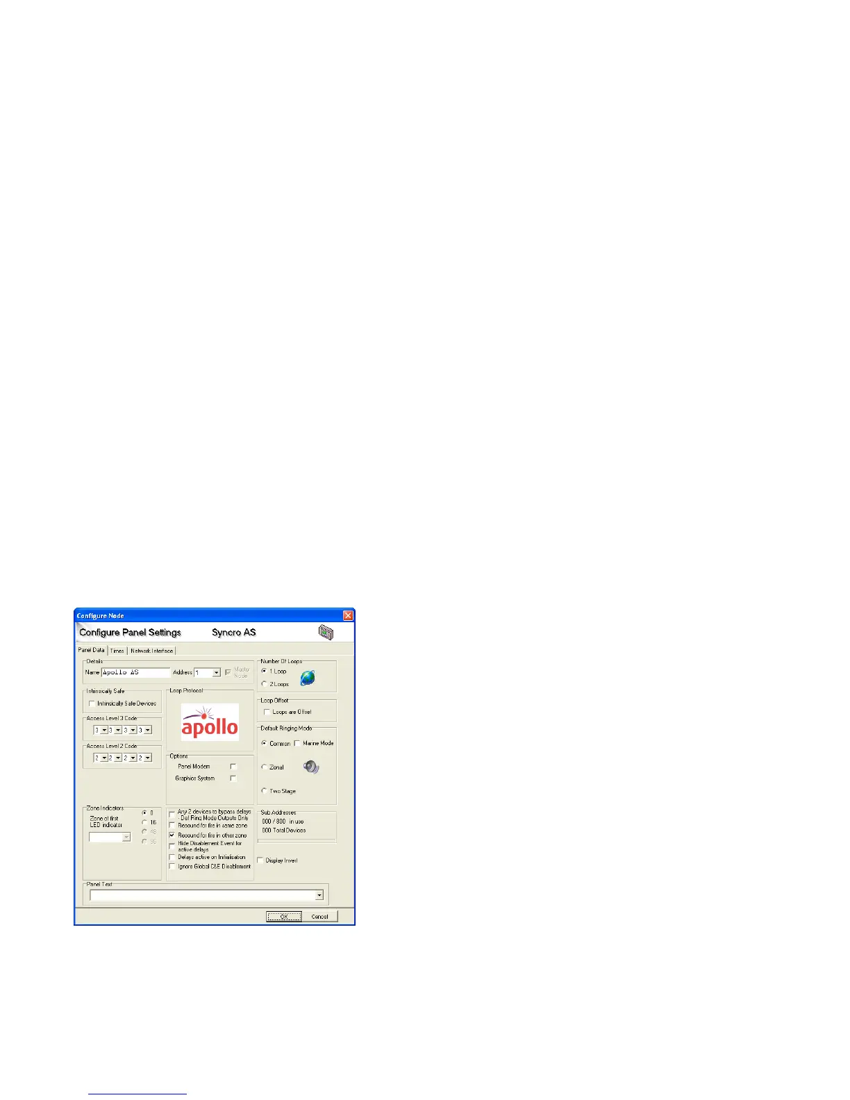
18.1 Panel settings
There are a number of attributes for the panel which can be changed using the configuration programme as shown below.
18.1.1. Panel name
By default the panel name will be set to match the protocol that the panel is
configured to communicate with. I.e. Apollo panel, Argus Vega panel or
Hochiki panel.
If the panel is part of a network of panels, it can be useful to have a panel
name, which would normally describe its location such as the name of the
building or facility where the panel is mounted.
The panel name can be up to 15 characters long.
18.1.2. Panel address
To enable control panels to know about each other when connected to a
network, each panel must have a unique address. This is the node address
and should be a number between 1 and 64. Syncro ASM panels that do not
have a network card installed will always default to address 1.
18.1.3. Protocol
Control panels are supplied as Apollo, Argus Vega or Hochiki compatible.
The label inside the control panel showing the part number identifies which
protocol is being used by starting with either an H (Hochiki) an A (Apollo) or
a V (Argus Vega).
When making a configuration file, the correct protocol panel must be
selected. Repeater panels are protocol independent.
18.1.4. Number of loops
Control panels are supplied with 1 or 2 detection loops fitted. The configuration file should be created with the same number of loops
as the control panel for which it is destined.