Product Manuals/Man-1096M_SyncroAS Marine 16 Page 19 of 38
15. Remote control inputs
Five inputs are provided in the panel, which have default actions as described in the table below:
INPUT DEFAULT ACTION
FLT Operates outputs configured to operate on fault condition.
RES Resets the control panel
INT Operates all sounder outputs intermittently
CNT Operates all sounder outputs continuously
SIL Acknowledges the alarm (silences all sounders)
NOTE: The RES / INT / CNT / SIL inputs should only be available at Access Level 2. Care must be taken to ensure these inputs
cannot be operated without some form of access control in order to maintin conformity to EN54-2.
All inputs can be re-programmed to have a different action, delay, zone and location message using the PC configuration programme
or front panel controls (at Access level 3)
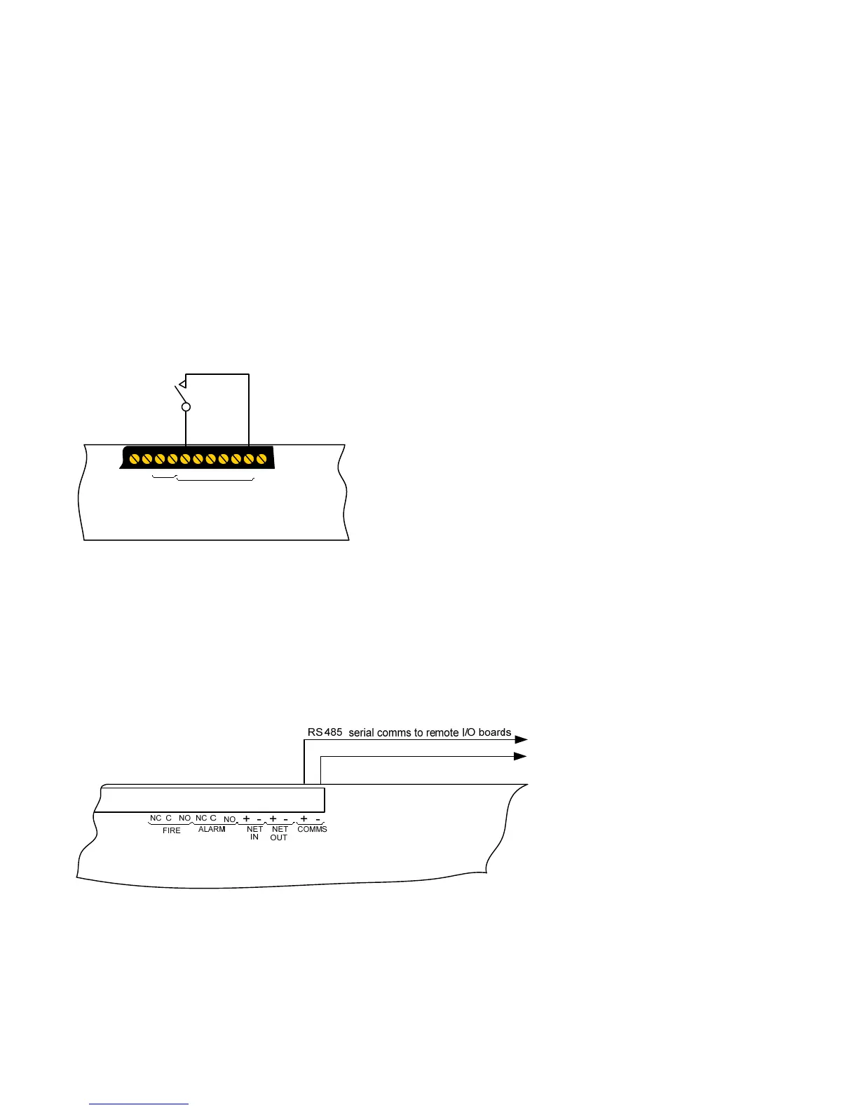
To activate the inputs, the 0V connection is connected to the input(s) as shown below.
All inputs are non-latching as default.
The line impedance should be less than 50 ohms for reliable operation.
16. Remote I/O serial bus
The Syncro ASM control panel has a serial communications bus to which additional I/O, relay, sounder and conventional detection
zone boards may be connected. The serial bus also supports up to 15 of the full function Syncro View repeater panels.
Up to 32 I/O units can be connected to the serial bus and these can be a mix of any type.
Limited numbers of these units may be connected to the panel’s Auxiliary 24V supply however the fuse rating of the Auxiliary supply
and the effect of the extra power required on battery standby must be taken into consideration. Full details of power consumption
for devices that connect to the serial I/O bus can be found in the O&M manuals of the individual devices.