Product Manuals/Man-1096M_SyncroAS Marine 16 Page 9 of 38
6. Connecting to the panel
All connections to the panel are via 5mm pitch, 2.5mm
2
capacity, spring leaf terminal blocks. Care should be taken to use the correct
sized terminal screwdriver and not to over tighten the terminals.
If stranded cables are used then care should be taken to ensure that all strands are contained in the terminal and that there are not
any loose strands which may cause short circuits to other terminals or cables.
The mains connection should enter the enclosure via a knockout as near to the mains terminal block as possible and should be
segregated from all other wiring. Mains connection cables should be kept short and be secured together with a cable tie near the
mains terminal block to minimise the danger of them shorting to other parts of the equipment if they become disconnected.
The mains terminal block contains a F1.6A L250V fuse and must be replaced only with a fuse of the same type.
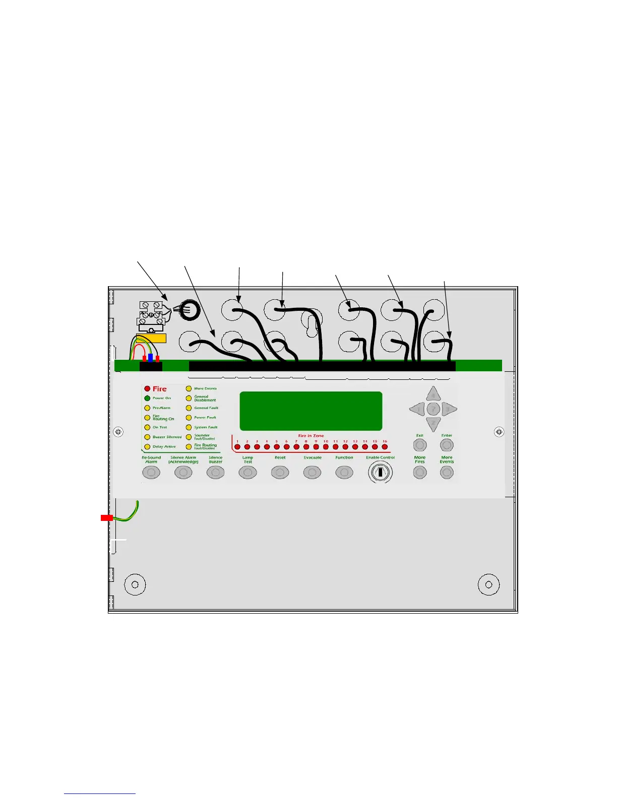
The diagram below shows the recommended cable routing for connections to the panel. The diagram shows the rear cable entry
points used. If top cable entry points are used then a similar arrangement should be employed.
To avoid the possibility of a confusing array of fault conditions, it is best to connect the system gradually so that faults can be
cleared on one circuit before connecting another.
Polarity must be observed carefully on any terminals with + or - markings and end of line devices must be fitted to all circuits which
connect to terminals that have had the supplied, end of line devices removed.
All wiring should be checked carefully before applying power to the control panel.
Do not connect or disconnect wiring with the power on.
N
L
E
230 V
OUT
NET
IN
NET COMMS
-+-+-+
ALARM
FIREFAULT
OUT
LOOP
IN
S2 L OO PS1
24V
AUX
REMOTE PSU
+
-
NOCNCNOCNCNOCNC
0VSILCNTINTRESFLT
-
+-
+-+-++
PF
--+
24V
-
INPUTS
OUT
+
MAINS
( secure with cable tie)
SOUNDERS
DETECTION
LOOPS
RELAYS
NETWORK
SERIAL
COMMS
OTHERS