114 Keysight Agile Signal Generator Service Guide
Assembly Replacement
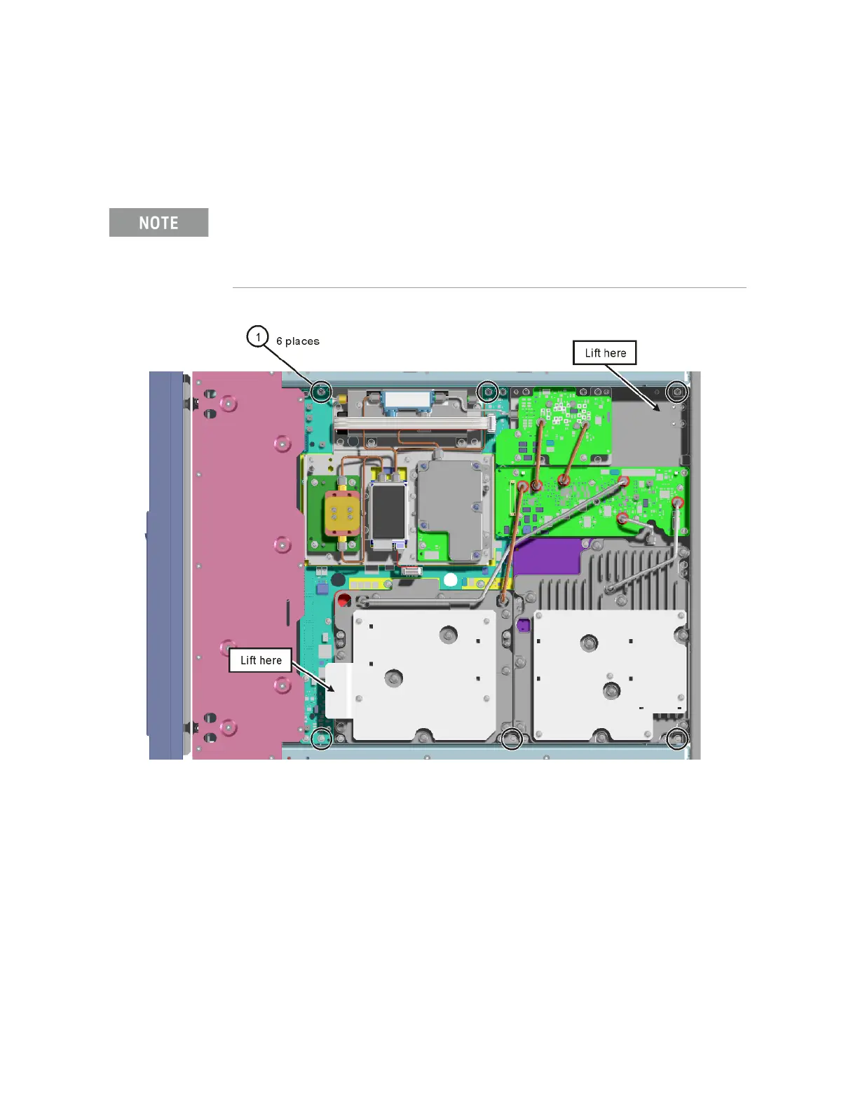
6. Refer to Figure 3-18. Remove the six screws (1) (0515-0664) that attach
the microdeck to the chassis. The microdeck can now be lifted out of the
chassis.
Figure 3-18 Remove Microdeck Screws
Replacement Procedure
1. Reverse the order of the removal procedure.
2. Recommended torque for all screws is 9 in–lbs.
3. Recommended torque for all cable connectors is 9 in–lbs.
4. Perform the post-repair service procedure and performance tests that
pertain to this replacement procedure, see Chapter 4, “Post-Repair
Procedures and Operational Performance Verification.”.
Take care to remove the correct screws that attach the microdeck to the chassis. They are
located close to other screws that do not need to be removed. All six of the microdeck screws
are the same length (12 mm). If you have removed a screw that is shorter than the other screws
you have probably removed a screw from an incorrect location and the microdeck will not be
able to be removed.