Keysight Agile Signal Generator Service Guide 141
Assembly Replacement
CPU Board Replacement
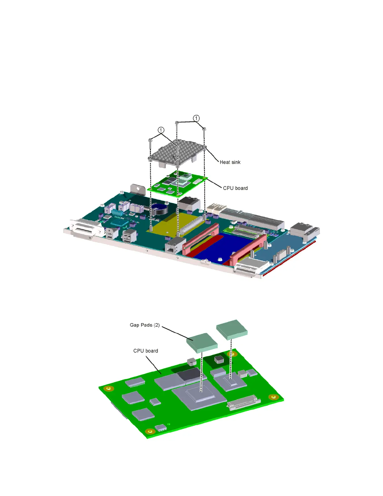
1. Refer to Figure 3-37. Using the T-10 driver, remove the 4 screws (1)
(0515-2141) that attach the CPU board to the carrier board. Remove the
heat sink. Carefully lift the CPU board to disengage from the connector
and lift off of the carrier board.
Figure 3-37 CPU Board Replacement
2. Refer to Figure 3-38. Before replacing the CPU board, attach the two gap
pads to the location shown.
Figure 3-38 CPU Gap Pads