5-12 Keysight N5221A/22A Service Guide
Theory of Operation
Synthesized Source Group Operation
5-
Rear Panel Interconnects
The A19 test set motherboard includes the following rear panel interconnects.
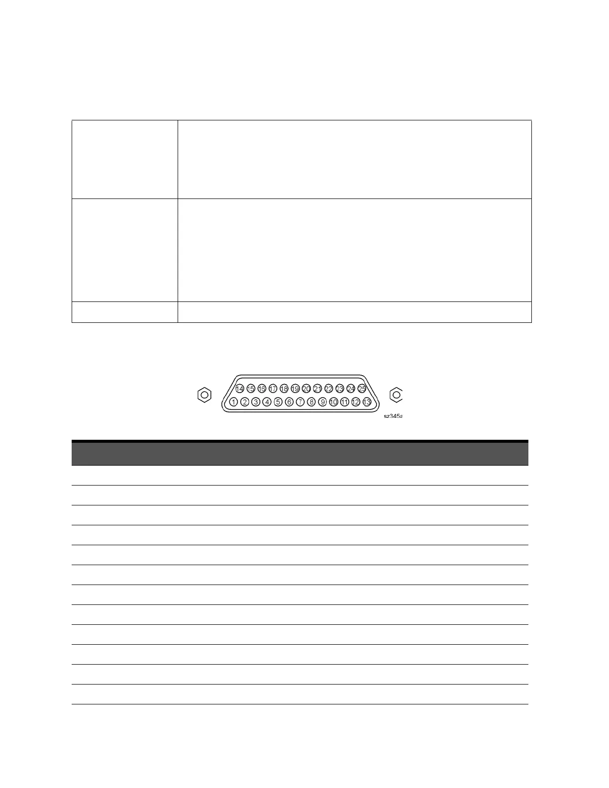
TEST SET I/O A DB-25 female connector that is used to control external test sets. The external test set bus
consists of 13 multiplexed address and data lines, three control lines, and an open-collector
interrupt line. Pin assignments are listed in
Table 5-1 on page 5-12.
Up to 16 test sets may be “daisy-chained” on the bus at one time.
The Test Set I/O is not compatible with 8753 network analyzer test sets.
HANDLER I/O A rectangular 36-pin, female connector providing four independent parallel input/output
ports, nine control signal lines, one ground, and a power supply line. This connector has Type
2 output pin assignments as listed in
Table 5-2 on page 5-13.
All signals are TTL-compatible. Data input/output ports consist of two 8-bit output ports (Port
A and Port B) and two 4-bit bidirectional ports (Port C and Port D).
Connector settings can be changed using SCPI and COM commands. The settings are not
accessible from the front panel.
PWR I/O
A DB-9 female connector. Pin assignments are listed in
Table 5-3 on page 5-14.
Table 5-1 TEST SET I/O Connector Pin Assignments
DB-25 Female Connector
Pin Numbers Name Function
1 SEL0 TTL out, test set select bit 0, tied to 0 V
2 Sweep Holdoff In TTL in, low level holds off sweep
3–6 AD12–AD8 TTL I/O, address and latched data
7 GND 0 V, ground reference
8 LAS TTL out, active low address strobe (1 μs min)
9–11 AD4–AD2 TTL I/O, address and latched data
12 GND 0 V, ground reference
13 Interrupt In TTL in, low level (10 μs min) aborts sweep
14 +22 V +22 Vdc, 100 mA max.
15–16 SEL1–2 TTL out, test set select bits 1-2, tied to 0 V
17 AD11 TTL I/O, address and latched data
18 SEL3 TTL out, test set select bit 3, tied to 0 V