Chapter 1 17
Introducing the N8241/2A AWGs
Front Panel Interface
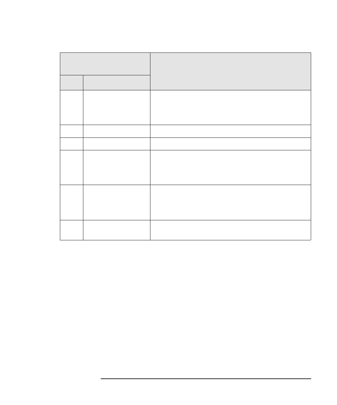
5 CH 1/CH2 Out The CH 1 OUT and CH 2 OUT positive (+) connectors are
used for single-ended operation. Use both the positive (+)
and negative (-) connectors for differential operation. Refer
to “Signal Conditioning” on page 84 for more information.
6 AUX PORT The AUX port is reserved for future applications.
7DATA PORT The data port is reserved for future applications.
8
TRIGGERS 1/2/3/4
There are four SMB female trigger input connectors that are
used to control the waveforms in the sequencer and create
event-based signal simulation. The connectors support
TTL/CMOS, ECL, and PECL logic levels.
9 MARKERS 1/2/3/4 There are four SMB female marker output connectors that
can be used for triggering or system synchronization. The
connectors are 3.3V TTL/CMOS 30 ohm series terminated.
The output is capable of driving a 50 ohm load.
10 Power Switch The power switch is toggled to either the ON or STANDBY
position.
Item Description
# Name