Getting Started 1
Keysight U1610/20A User’s Guide 33
Figure 1-8 Insulation cover
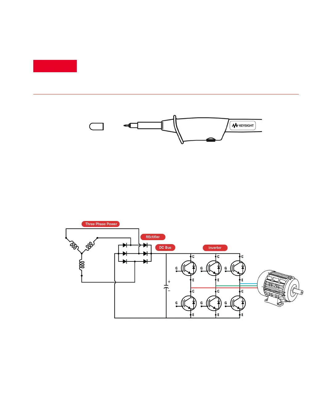
An example of how a fully isolated input channels handheld scope monitors the
output voltage of a PWM inverter drive and the gate control signals of an
Insulated Gate Bipolar Transistor (IGBT) is shown in Figure 1-9. Channel 1 is
connected to the output voltage of the PWM AC drive and Channel 2 is connected
to the transistor input, where the signals come from the control board. For a
complete floating measurement, the probe reference lead for each channel is
connected to the circuitry.
Figure 1-9 Probing the VFD IGBT control signal and IGBT
output
Connect the insulation cover over the probe tip when the hook clip is not
used to prevent any electrical shock. This also helps to avoid unwanted
interconnection between the two probes when both ground clips are
connected.