101
Making Time-Gated Measurements
Gated LO Measurement
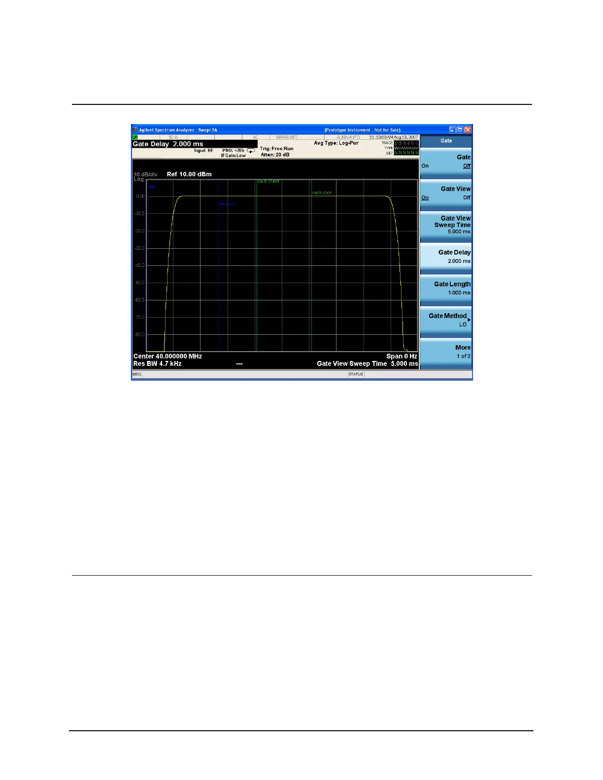
Figure 8-6 Viewing the Gate Settings with Gated LO
The blue vertical line (the far left line outside of the RF envelope) represents the location equivalent to a zero
gate delay.
The vertical green parallel bars represent the gate settings. The first (left) bar (GATE START) is set at the delay
time while the second (right) bar (GATE STOP) is set at the gate length, measured from the first bar. The trace
of the signal in this time-domain view is the RF envelope. The gate signal is triggered off of the positive edge of
the trigger signal.
When positioning the gate, a good starting point is to have it extend from 20% to 80% of the way through the
pulse.
While gate view mode is on, move the gate delay, length and polarity around. Notice the changes in the
vertical gate bars while making your changes. Set the gate delay, length and polarity back to the step 3
settings.
NOTE The analyzer time gate triggering mode uses positive edge, negative edge, and level triggering.
7 Turn the gate view off. • Press Sweep/Control,
Gate, Gate View (Off).
See Figure 8-7.
Step Action Notes

 Loading...


