136
Measuring Digital Communications Signals
Spectrum Emission Mask Measurements
Troubleshooting hints
This spectrum emission mask measurement can reveal degraded or defective parts in
the transmitter section of the UUT. The following examples are those areas to be
checked further.
• Faulty DC power supply control of the transmitter power amplifier.
• RF power controller of the pre-power amplifier stage.
• I/Q control of the baseband stage.
• Some degradation in the gain and output power level of the amplifier due to the
degraded gain control and/or increased distortion.
• Some degradation of the amplifier linearity or other performance characteristics.
7 Initiate the spectrum
emission mask
measurement.
• Press Meas, More,
Spectrum Emission
Mask.
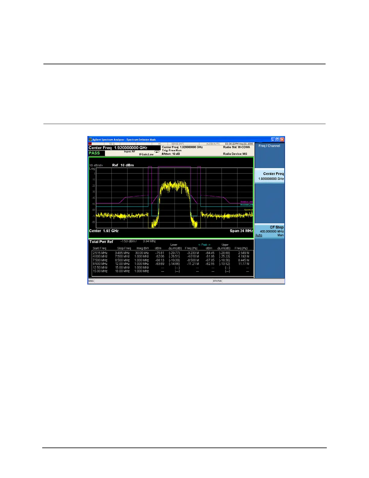
The Spectrum Emission Mask
measurement result should look like
Figure 9-16. The text window shows the
reference total power and the absolute
peak power levels which correspond to
the frequency bands on both sides of the
reference channel.
Figure 9-16 Spectrum Emission Mask Measurement Result - (Default) View
Step Action Notes

 Loading...


