99
Making Time-Gated Measurements
Connecting the Instruments to Make Time-Gated Measurements
Connecting the Instruments to Make Time-Gated Measurements
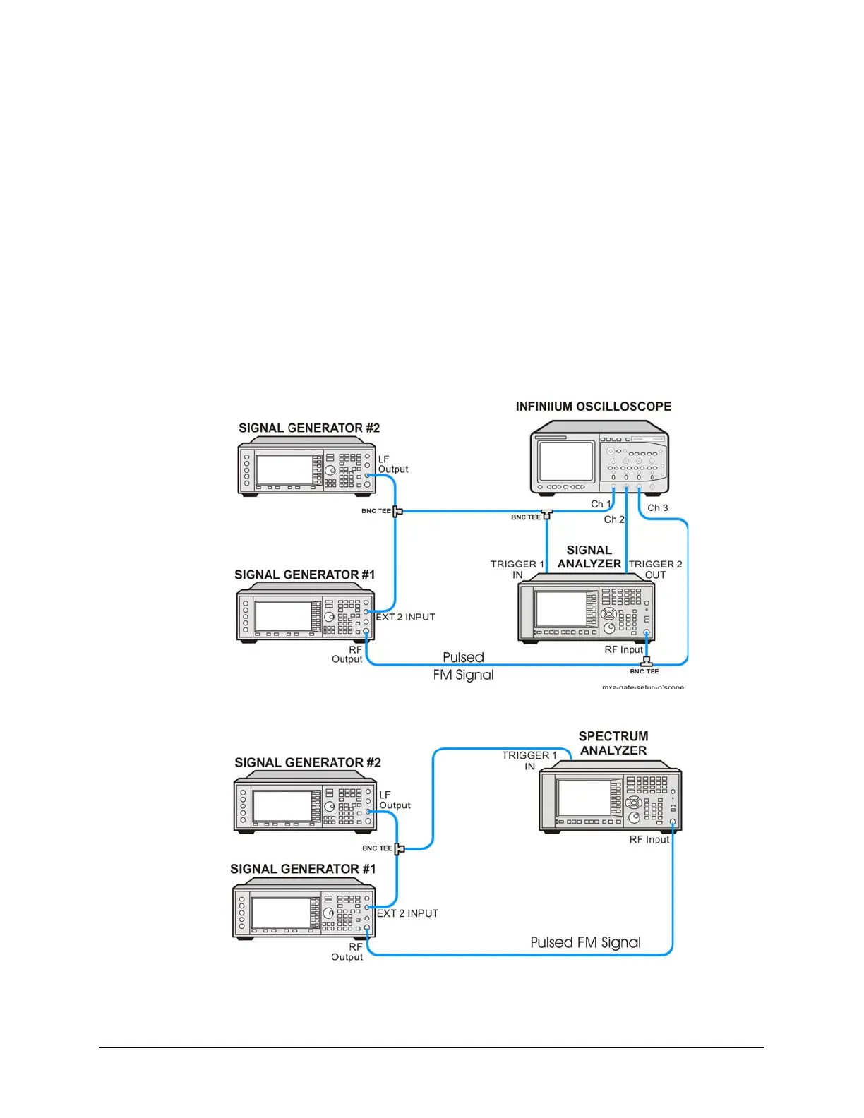
Figure 8-4 shows a diagram of the test setup. ESG #1 produces a pulsed FM signal
by using an external pulse signal. The external pulse signal is connected to the front
of the ESG #1 to the EXT 2 INPUT to control the pulsing. The pulse signal is also
used as the trigger signal. The oscilloscope is useful for illustrating timing
interactions between the trigger signal and the gate. The Gate View feature of the
X-Series signal analyzer could be used in place of the oscilloscope.
Using this measurement setup allows you to view all signal spectra on the spectrum
analyzer and all timing signals on the oscilloscope. This setup is helpful when you
perform gated measurements on unknown signals. If an oscilloscope is not available,
begin by using the Gate View feature to set up the gate parameters and then turn Gate
View Off to view the signal spectra, refer to Figure 8-5
Figure 8-4 Instrument Connection Diagram with Oscilloscope
Figure 8-5 Instrument Connection Diagram without Oscilloscope

 Loading...


