98
Making Time-Gated Measurements
Generating a Pulsed-RF FM Signal
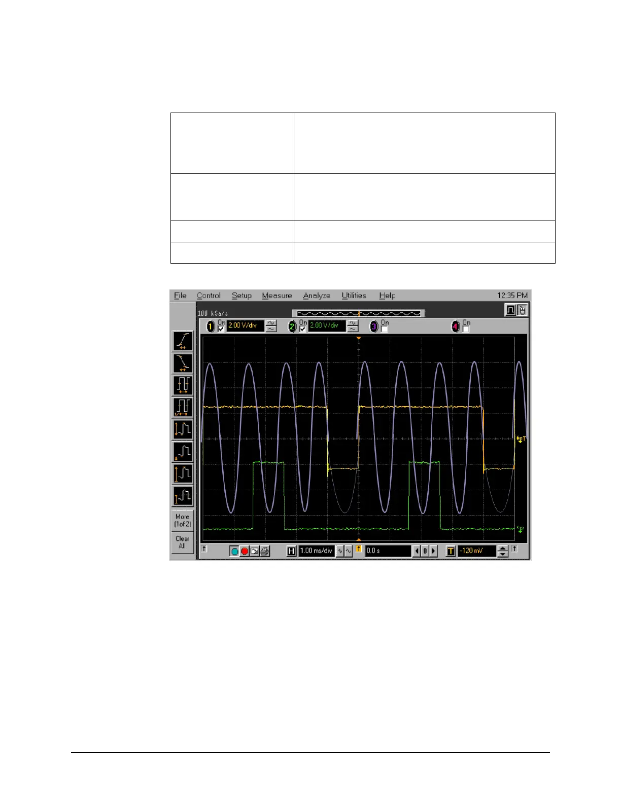
Figure 8-3 Viewing the Gate Timing with an Oscilloscope
Figure 8-3 oscilloscope channels:
1. Channel 1 (yellow trace) - the trigger signal.
2. Channel 2 (green trace) - the gate signal (gate signal is not active until the gate is
on in the spectrum analyzer).
3. Channel 3 (purple) - the RF output of the signal generator.
Channel 2 ON, 500 mV/div, OFFSET = 2 V, DC coupled, 1 M Ω input,
connect to the signal analyzer TRIGGER 2 OUT
connector. Adjust channel 2 settings as needed when gate
is active.
Channel 3 ON, 500 mV/div, OFFSET = 0 V, Timebase = 20 ns/div, DC
coupled, 50 Ω input, connect to the ESG RF OUTPUT
pulsed-RF signal. Adjust channel 3 settings as necessary.
Channel 4 OFF
Trigger Edge, channel 1, level = 1.5 V, or as needed
Table 8-4 Keysight Infiniium Oscilloscope with 3 or more input channels: Instrument
Connections

 Loading...


