97
Making Time-Gated Measurements
Generating a Pulsed-RF FM Signal
Digitizing oscilloscope setup
If you are using a digitizing oscillascope, set up the oscilloscope to view the trigger,
gate and RF signals (see Figure 8-3 for an example of the oscilloscope display):
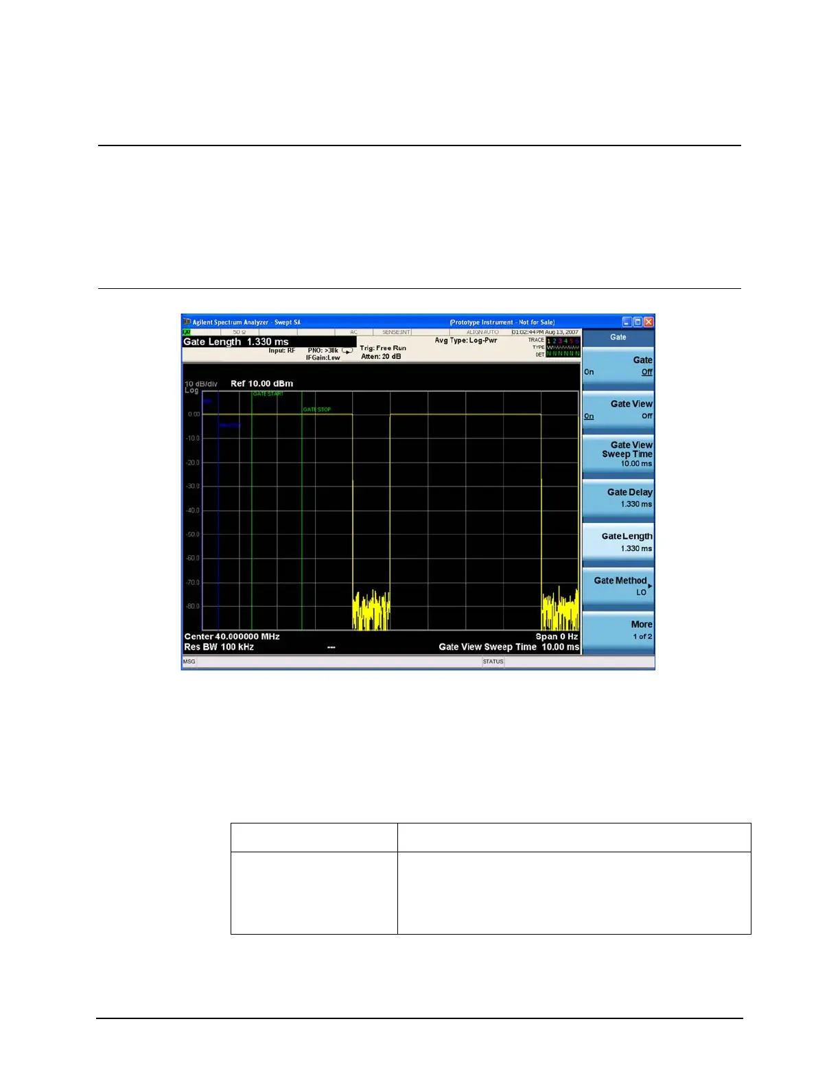
7 Set the RBW to auto,
gate view to off, gate
method to LO, and
gate to on.
a. Press Sweep/Control, Gate, Gate
View (Off).
b. Press BW, Res BW (Auto).
c. Press Sweep/Control, Gate, Gate
Method, LO.
d. Press Gate (On).
Figure 8-2 Gated RF Signal with Auto RBW
Step Action Notes
Table 8-4 Keysight Infiniium Oscilloscope with 3 or more input channels: Instrument
Connections
Timebase 1 ms/div
Channel 1 ON, 2 V/div, OFFSET = 2 V, DC coupled, 1 M Ω input,
connect to the pulse signal (ESG LF OUTPUT or pulse
generator OUTPUT). Adjust channel 1 settings as
necessary.

 Loading...


