64
Making Distortion Measurements
Identifying Analyzer Generated Distortion
Identifying Analyzer Generated Distortion
High level input signals may cause internal analyzer distortion products that could
mask the real distortion measured on the input signal. Using trace 2 and the RF
attenuator, you can determine which signals, if any, are internally generated
distortion products.
Using a signal from a signal generator, determine whether the harmonic distortion
products are generated by the analyzer.
Step Action Notes
1 Set up the signal
generator.
a. Set the frequency to 200 MHz.
b. Set the amplitude to 0 dBm.
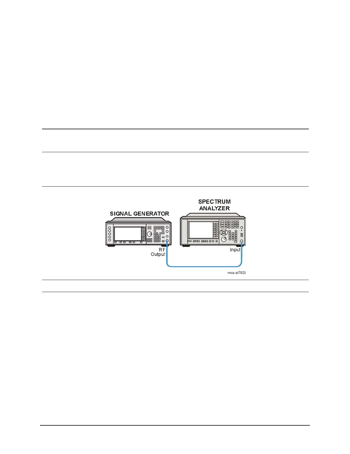
2 Connect the source RF
OUTPUT to the
analyzer RF INPUT as
shown.
3 Select the mode. • Press Mode, Spectrum Analyzer.
4 Set the analyzer center
frequency, span, and
video bandwidth.
a. Press FREQ Channel, Center
Freq, 400, MHz.
b. Press SPAN X Scale, Span, 500,
MHz.
c. Press BW, Video BW, 30, kHz.
The signal produces harmonic
distortion products (spaced 200
MHz from the original 200 MHz
signal) in the analyzer input mixer
as shown in the following
graphic. See Figure 6-1

 Loading...


