88
Measuring Noise
Improving Phase Noise Measurements by Subtracting Signal Analyzer Noise
Improving Phase Noise Measurements by Subtracting Signal Analyzer
Noise
Making noise power measurements (such as phase noise) near the noise floor of the
signal analyzer can be challenging where every dB improvement is important.
Utilizing the analyzer trace math function Power Diff and 3 separate traces allows
measurement of the DUT phase noise in one trace, the analyzer noise floor in a
second trace and then the resulting subtraction of those two traces displayed in a
third trace with the analyzer noise contribution removed.
Step Action Notes
1 Set up the signal sources. a. Setup an unmodulated signal.
b. Set the source frequency to 1.96
GHz.
c. Set the source amplitude to –30 dBm.
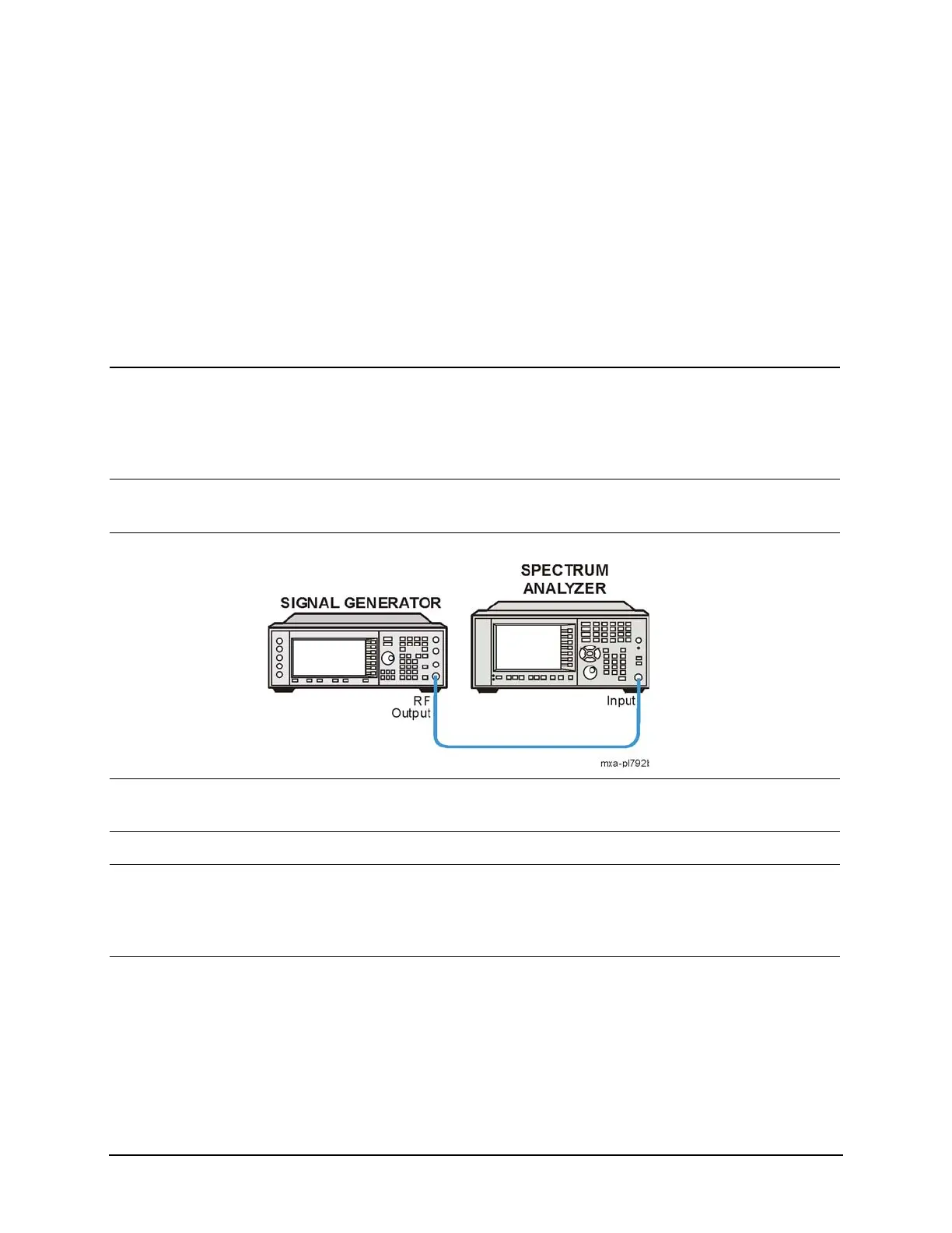
2 Instrument setup. • Connect the source RF OUTPUT to the
analyzer RF INPUT as shown.
3 Set the analyzer to the
Spectrum Analyzer mode.
• Press Mode, Spectrum Analyzer. This enables the spectrum
analyzer measurements.
4 Preset the analyzer. • Press Mode Preset.
5 Tune to the unmodulated
carrier, adjust the span and
RBW.
a. Press FREQ Channel, Auto Tune.
b. Press Span, Span, 200, kHz.
c. Press BW, Res BW, 910, Hz.
6 Measure and store the DUT
phase noise plus the
analyzer noise.
a. Press Trace/Detector, Select Trace,
Trace 1, Trace Average
After sufficient averaging:
b. Press View/Blank, View
Allow time for sufficient
averaging before initiating
action b.
See Figure 7-11.

 Loading...


