185
Option Esc External Source Control
Using the M1970 Series Mixers with X-Series Signal Analyzers (Option EXM)
Avoiding waveguide flange damage
Install the waveguide flange cap whenever the mixer is not connected to a device
under test. This will protect the waveguide flange mating surface.
Mixer waveguide connections
Assure the shoulder of the mixer waveguide flange is properly aligned with the
flange of the device under test. To ensure proper mating, it is important to tighten all
screws equally. To do this, tighten opposed screws in pairs by a small amount until
all are snug. Final torque must not exceed 7 in pounds.
For additional information regarding use with a particular X-Series analyzer, refer to
that analyzer's User's and Programmer's Reference Guide.
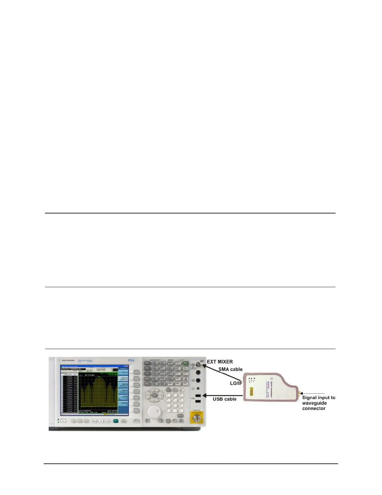
Equipment set up
The following examples explain how to connect the external mixers to the signal
analyzer, and how to use the signal-identification functions.
Step Action Notes
1 SMA connection a. Connect an SMA
cable from the mixer
to the spectrum
analyzer EXT MIXER
front panel SMA.
The torque for the SMA cables and adapters should not
exceed 8 in-lbs.
The LO/IF connection between the mixer and the signal
analyzer must be in place before the USB cable from the
mixer is connected. Connecting the USB cable
automatically triggers the LO adjustment, and if the LO/IF
cable is not connected the adjustment will not complete
and an error will occur.
2 USB connection a. Connect a USB
cable from the mixer
to the spectrum
analyzer.
When a connection is made, the green LED on the mixer
lights up indicating that the mixer has power and the
processor inside the mixer is running. The spectrum
analyzer is automatically switched to external mixing
mode, and the mixer model number and mixer option are
used to set the start and stop frequencies for the mixing
band.

 Loading...


