6-50 Applied Operation PLZ-4W
6.8.4 External Control of CR Mode
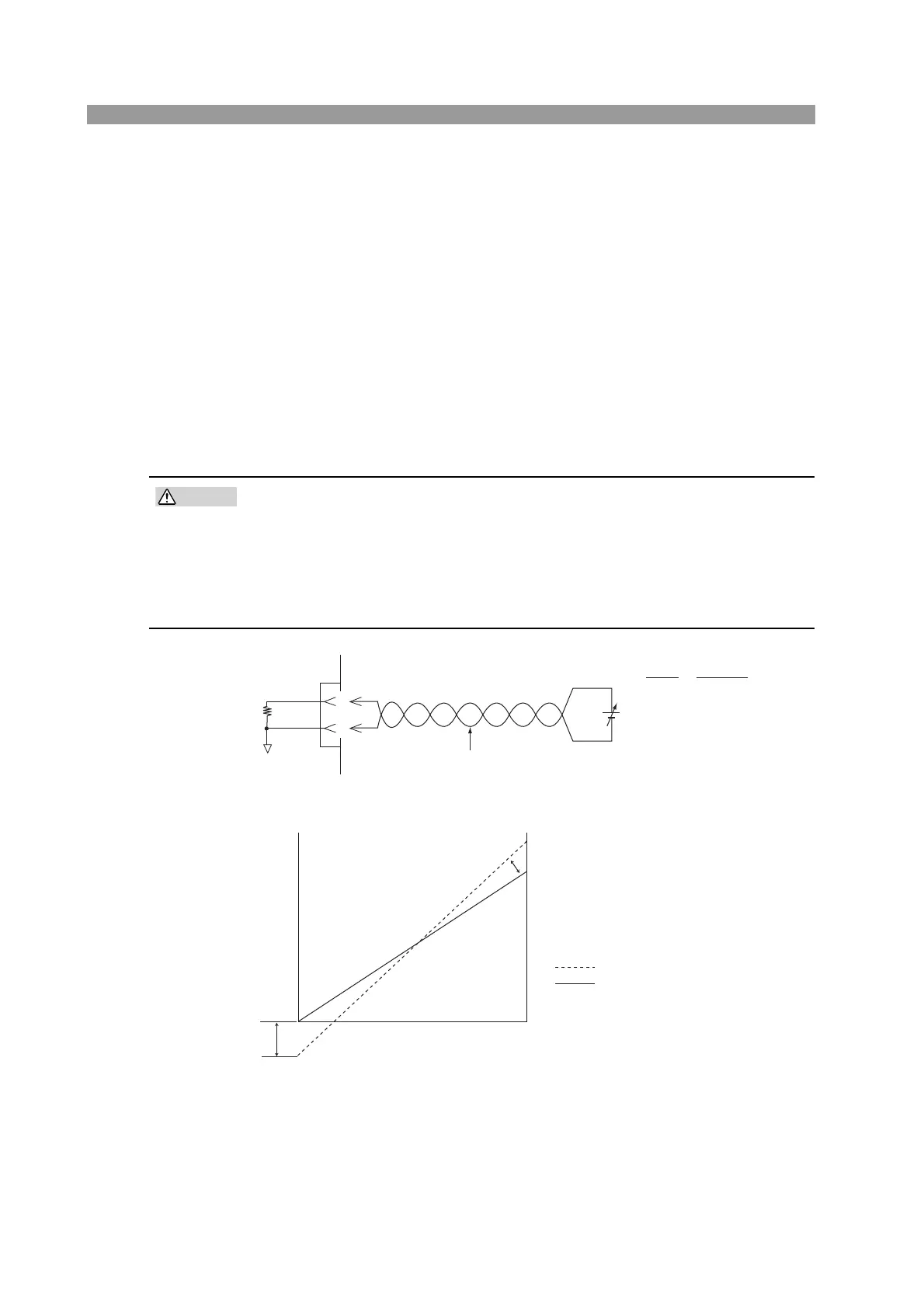
The external control of CR mode can be carried out using external voltage or exter-
nal resistance. The resistance varies proportionally to the external voltage or exter-
nal resistance.
(1) External voltage control
Applying an external voltage in the range of 0 V to 10 V to the PLZ-4W produces a
resistance proportional to the change.
The external voltage of 0 V and 10 V correspond to the maximum and minimum
resistances of the range, respectively.
Connected pins: J1-1 (signal), J1-3 (common)
• The maximum voltage that can be applied across pins 1 and 3 of the J1
connector is 11 V. Applying a voltage exceeding this value can damage
the PLZ-4W.
• Pin 3 of the J1 connector is connected the negative load input terminal. To
prevent damaging the PLZ-4W, be sure not to let the wire of pin 3 touch
any other pins.
Fig. 6-28 Equivalent circuit
Fig. 6-29 Control the resistance using external voltage
■ The setup procedure is the same as with CC mode.
See page 6-45 “Setup procedure for external voltage control”.
1
3
J1
Ein
1
R
0
Ein: External voltage
0 Ein 10 V
R
0: Operating resistance
Gm: Rated conductance
A COM
EXT R/V CONT
Gm
Gm
0S
External voltage Ein
0V
: Rated conductance (S)
: Conductance (before adjustment)
: Conductance (after adjustment)
Conductance
10V
Offset
adjustment