PLZ-4W Applied Operation 6-57
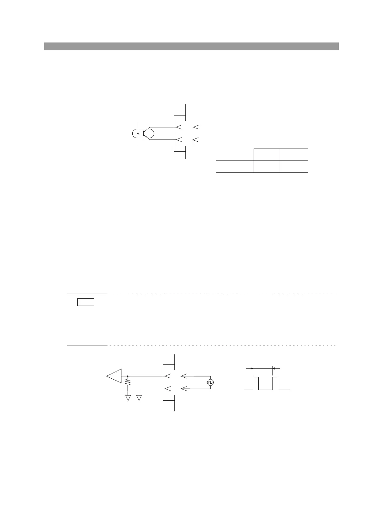
Status signal output
To externally monitor the load on/off condition, the output signal across pins 13 and
17 of the J1 connector is monitored.
Fig. 6-41 Equivalent output circuit
6.8.8 Trigger Signal Control
The trigger signal input clears the pause during sequence execution. This is used to
synchronize with external equipment.
Trigger signal input
Apply a signal across pins 11 and 12 of the J1 connector. The maximum allowable
voltage is 5 V, and the minimum pulse width is 10 s.
• The trigger signal output is generated at the rising edge of the pulse signal applied
to the trigger input connector.
• The input terminal is connected to A COM of the J1 connector through approxi-
mately 100 k of resistance. The maximum allowable voltage is 5 V, and the
operation threshold level is TTL.
Fig. 6-42 Equivalent input circuit
13
17
Maximum applied voltage 30 V
Maximum current 8 mA
Load on Load off
Photocoupler ON OFF
A COM
J1
100 ms or more
Allow 100 ms or more
between input pulses.
0 V
11
12
Approx. 100
k