6-52 Applied Operation PLZ-4W
6.8.5 External Control of CP Mode
The external control of CP mode can be carried out using external voltage or exter-
nal resistance. The wattage varies in proportion to the external voltage or external
resistance.
(1) External voltage control
Applying an external voltage in the range of 0 V to 10 V to the PLZ-4W produces a
wattage proportional to the change.
The wattage corresponding to the external voltage of 0 V is 0 W; the wattage corre-
sponding to the external voltage of 10 V is 100 % of the specified range.
Connected pins: J1-1 (signal), J1-3 (common)
• The maximum voltage that can be applied across pins 1 and 3 of the J1
connector is 11 V. Applying a voltage exceeding this value can damage
the PLZ-4W.
• Pin 3 of the J1 connector is connected the negative load input terminal. To
prevent damaging the PLZ-4W, be sure not to let the wire of pin 3 touch
any other pins.
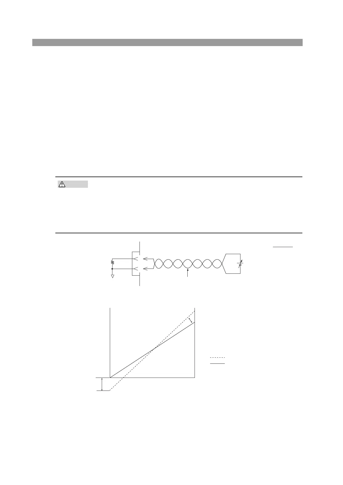
Fig. 6-32 Equivalent circuit
Fig. 6-33 Control the resistance using external voltage
■ The setup procedure is the same as with CC mode.
See page 6-45 “Setup procedure for external voltage control”.
Po ≈
Pm × Ein
10
Po: Input power
Pm: Rated power
Ein: External voltage
0 ≤ Ein ≤ 10 V
1
3
J1
Ein
A COM
EXT R/V CONT
Approx. 10 kΩ
–
+
Twist
Vm
Vm
0 V
External voltage Ein
0 V
: Rated voltage
: Input voltage (before adjustment)
: Input voltage (after adjustment)
Input current Vo
10 V
Offset
adjustment
Full scale adjustment
 Loading...