PLZ-4W Applied Operation 6-59
6.8.10 Alarm Signal Control
An alarm can be activated using an external control signal. In addition, the status
signal output can be used to monitor the alarm condition.
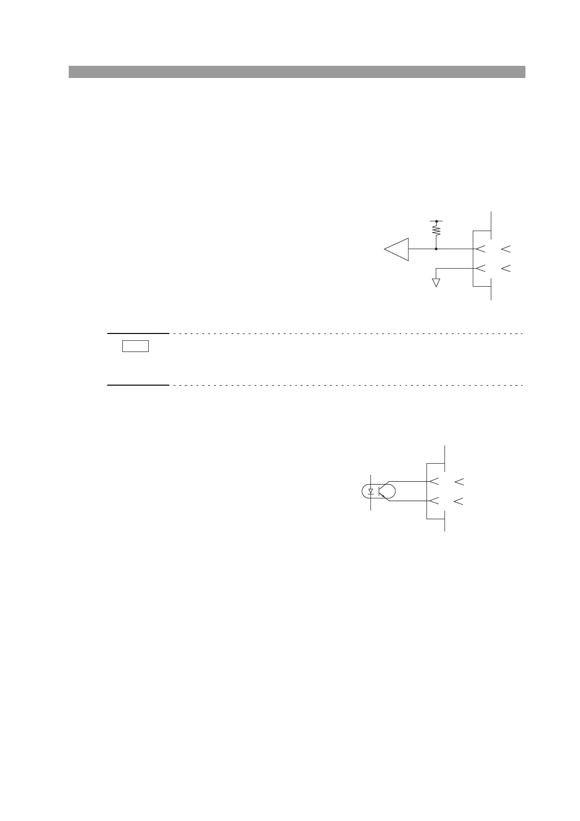
Alarm signal input
Connect the external signal across pins
10 and 12 of the J1 connector. An alarm
is activated on a low level signal.
• The alarm input terminal is connected to +5 V of the J1 connector through approx-
imately 10 k of resistance. The maximum allowable voltage is 5 V, and the oper-
ation threshold level is TTL.
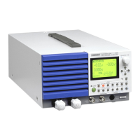
Status signal output
To externally monitor the alarm
condition, the output signal across
pins 16 and 17 of the J1 connector
is used.
The output is turned on when
OVP, OCP, OPP, OHP, REV or
UVP trips or when an external
alarm signal is applied.
Fig. 6-45 Equivalent input circuit
Photocoupler (P.C)
17
16
Maximum applied voltage 30 V
Maximum current 8 mA
Fig. 6-46 Equivalent output circuit