Modbus use “Big Endian” of encoder mode,which means sending data with high byte in front and low byte
behind.
1). RTU mode
In RTU mode,there must be a idle of at least 3.5 characters between two frames.It use CRC-16 for data
check.
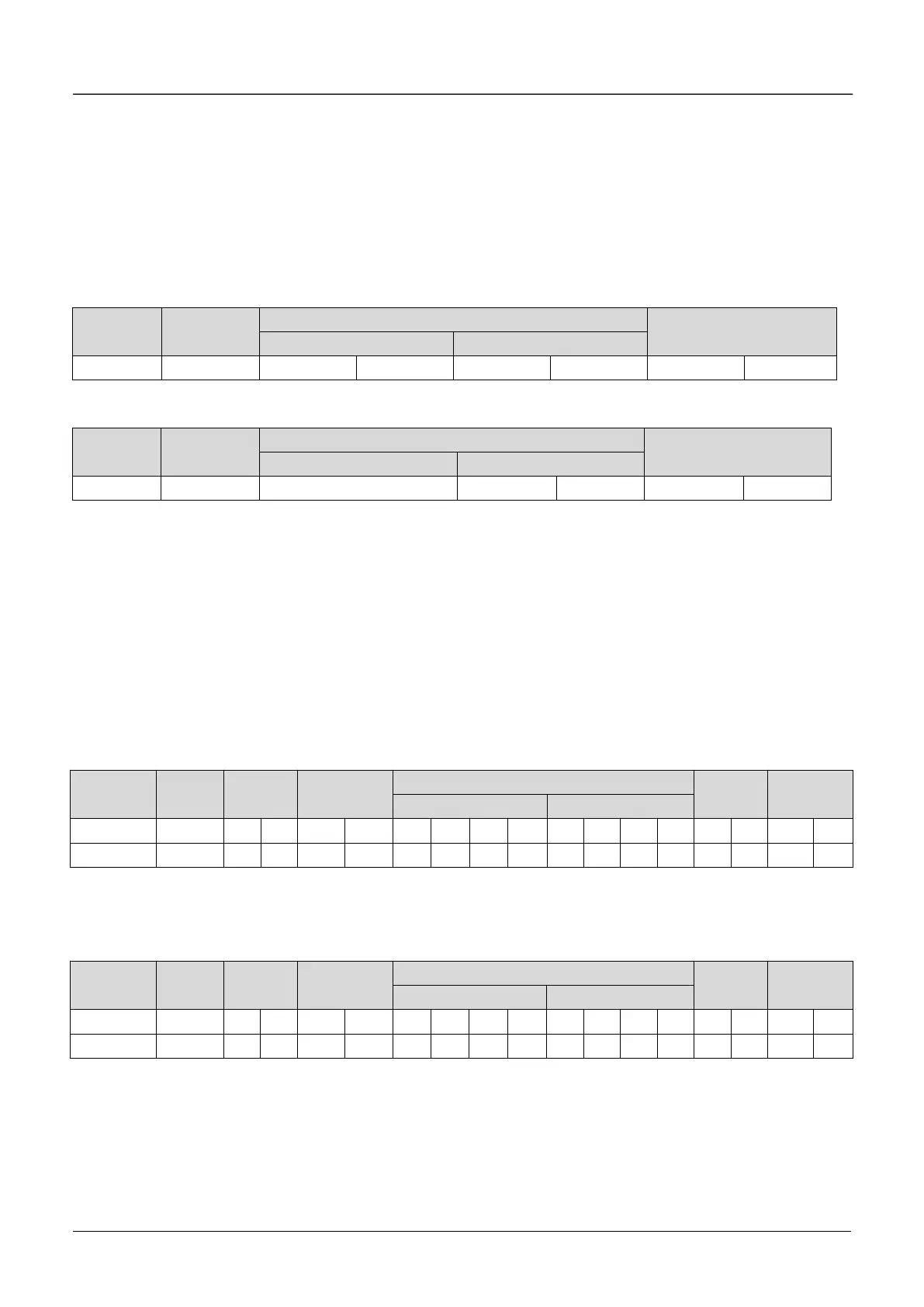
Following is an example for read the parameter of internal register 0101(A1.01) from No.5 slave.
Request frame:
Response frame:
Therein, checksum is CRC value.
2). ASCII mode
In
ASCII mode
, characters are used to start and end a frame. The colon “0x3A” is used to flag the start of a
message and each message is ended with a “0x0D,0x0D” combination. Except frame header and end of
frame,all other messages are coded in hexadecimal values, represented with readable ASCII characters.
Only the characters 0...9 and A...F are used for coding. Herein the data use LRC as error checksum.
Following is an example for writing value 4000(0x0FA0) into the parameter of internal register 0201(A2.01)
from No.5 slave.
Request frame:
Therein, the check code is LRC checksum,which value is equal to the complement of
(05+06+02+01+0x0F+0xA0).
Response frame:
VFD can set different delay time for response according to different application.For RTU mode,the actual
delay time for response is 3.5 characters interval at least.For ASCII mode,the actual delay time for response
is 1 ms at least.
 Loading...

