It is used to calculate the display value of rotary
speed in LED.
Display value=Operating speed*b4.07
Lower limit of frequency~
upper limit of frequency【5.00Hz】
Lower limit of frequency~
upper limit of frequency【10.00Hz】
Lower limit of frequency~
upper limit of frequency【15.00Hz】
Lower limit of frequency~
upper limit of frequency【20.00Hz】
Lower limit of frequency~
upper limit of frequency【25.00Hz】
Lower limit of frequency~
upper limit of frequency【30.00Hz】
Lower limit of frequency~
upper limit of frequency【35.00Hz】
Lower limit of frequency~ upper limit
of frequency【40.00Hz】
Lower limit of frequency~ upper limit
of frequency【45.00Hz】
Lower limit of frequency~ upper limit
of frequency【50.00Hz】
Lower limit of frequency~ upper limit
of frequency【10.00Hz】
Lower limit of frequency~ upper limit
of frequency【20.00Hz】
Lower limit of frequency~ upper limit
of frequency【30.00Hz】
Lower limit of frequency~ upper limit
of frequency【40.00Hz】
Lower limit of frequency~ upper limit
of frequency【50.00Hz】
These frequencies will be used in multi-step speed
operation, refer to the introductions of No.27,28,29
and 30 function of A6.00~A6.07.
6.16 Group C1
Process close-loop control
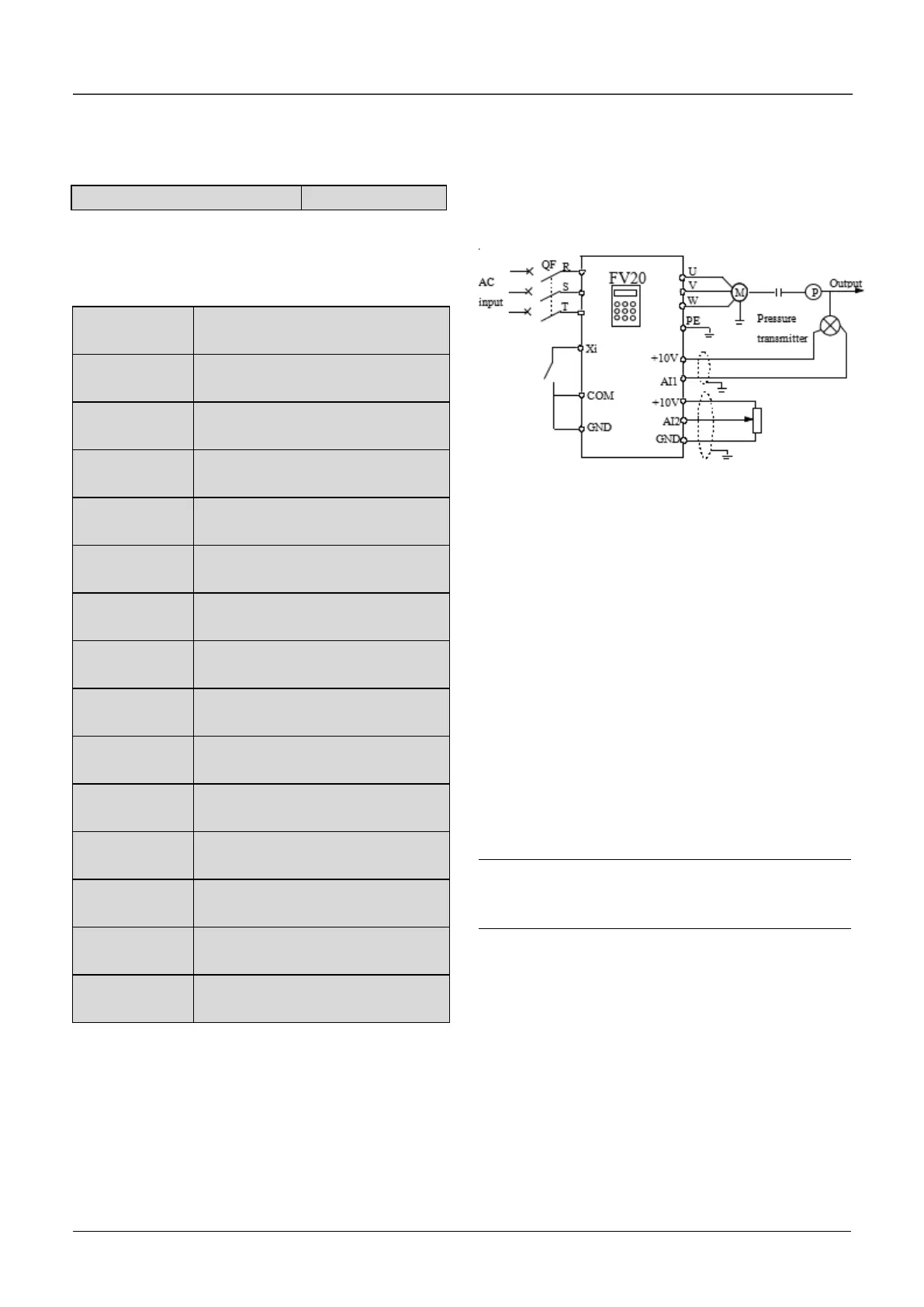
The process closed-loop control type of FV20 is
analog close-loop control. Fig.6-40 shows the
typical wiring of analog close-loop control.
Fig.6-40 Analog feedback control system with
internal process close-loop
Analog feedback control system:
An analog feedback control system uses a pressure
transmitter as the feedback sensor of the internal
close-loop.
As shown in Fig. 6-40, pressure reference (voltage
signal) is input via terminal AI2, while the feedback
pressure value is input into terminal AI1 in the form
of 4~20mA current signal. The reference signal and
feedback signal are detected by the analog channel.
The start and stop of the drive can be controlled by
terminal Xi.
The above system can also use a TG (speed
measuring generator) in close speed-loop control.
Note:
The reference can also be input via panel or serial
port.
Operating principles of internal process close-loop
of FV20 is shown in the Fig. 6-41
In the Fig, KP: proportional gain; Ki: integral gain
In Fig. 6-41, refer to C1.00~C1.14 for the definitions
of close-loop reference, feedback, error limit and
proportional and Integral parameters

 Loading...
