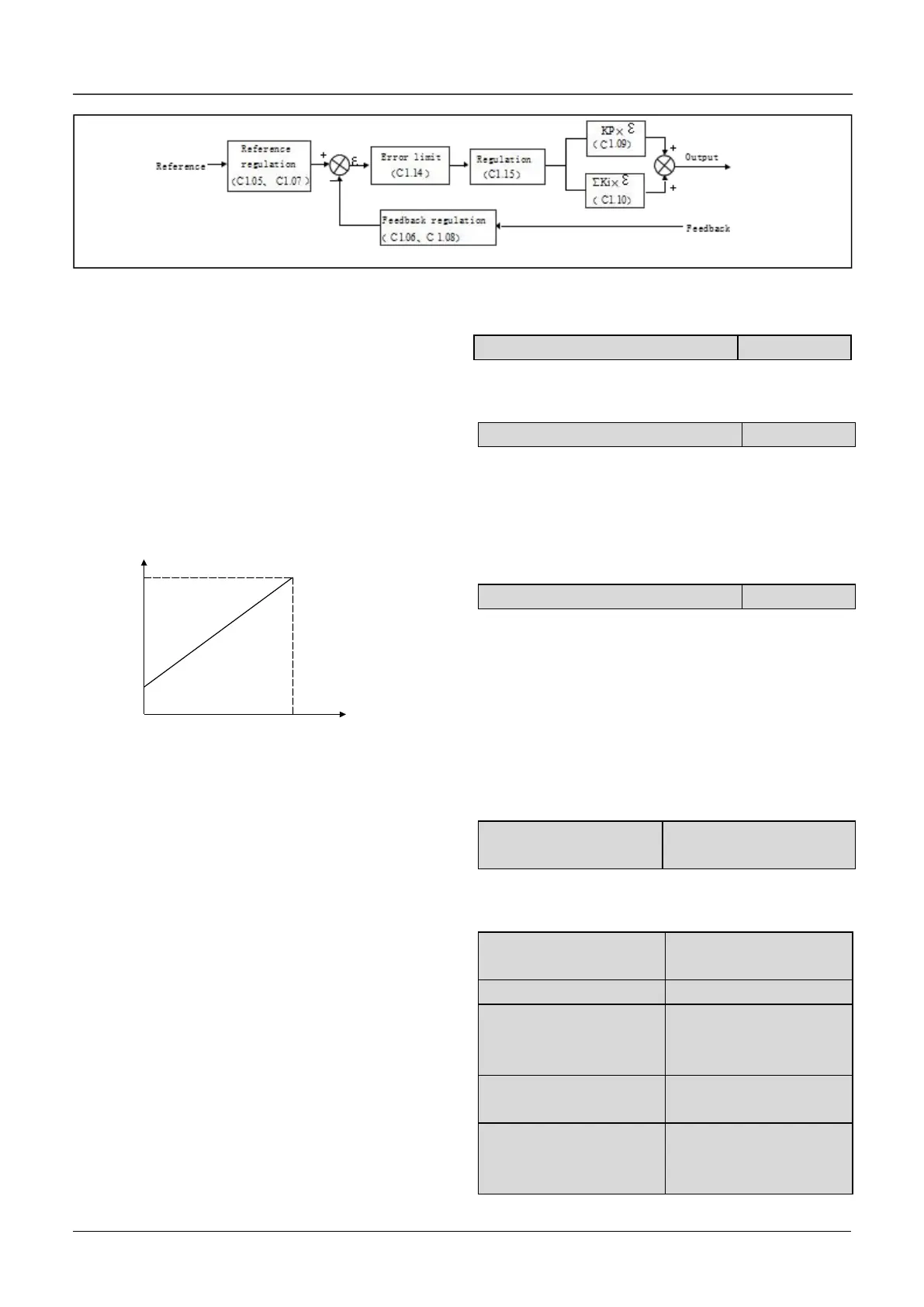
Fig.6-41 Principle diagram of process close-loop control
There are two features of internal close-loop of
FV20:
The relationship between reference and feedback
can be defined by C1.05~C1.08
For example: In Fig.6-40, if the reference is analog
signal of -10~10V, the controlled value is 0~1MP,
and the signal of pressure sensor is 4~20mA, then
the relationship between reference and feedback is
shown in Fig. 6-42.
Fig.6-42 Reference and feedback
After the control type is determined, follow the
procedures below to set close loop parameters.
1) Determine the close-loop reference and
feedback channel (C1.01 and C1.02);
2) The relationship between close-loop reference
and feedback value (C1.05 ~ C1.08) should be
defined for analog close-loop control;
3) Determine the close-loop regulation
characteristic, if the relationship between motor
speed and the reference is opposite, then set the
close-loop regulation characteristic as negative
characteristic(C1.15=1).
4) Set up the integral regulation function and
close-loop frequency presetting function (C1.16 ~
C1.18);
5) Adjust the close-loop filtering time, sampling
cycle, error limit and gain(C1.09~C1.14).
C1.00 Close-loop control function
C1.01 Reference channel selection
0: digital input
Take the value of C1.03 .
1: AI1 analog input.
2: AI2 analog input
3:Keyboard potentiometer analog voltage input.
C1.02 Feedback channel selection
0: AI1 analog input
1: AI2 analog input
2: AI1+ AI2
3: AI1-AI2
4: Min{ AI1,AI2}
5: Max{ AI1,AI2}
6: Pulse DI
Settings of AI are the same as above.
C1.03 Digital setting of
reference
This function can realize digital setting of reference
via panel or serial port.
C1.04 Close-loop speed
reference
C1.06 Feedback value
corresponding to the Min
reference
C1.08 Feedback value
corresponding to the Max
reference

 Loading...
