A2.09 Range of skip
frequency 2
A2.11 Range of skip
frequency 3
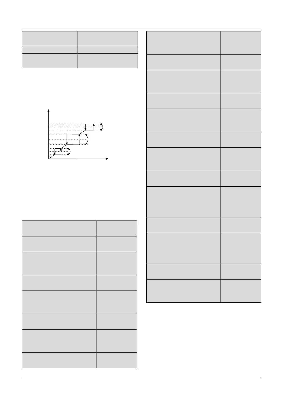
A2.06~A2.11 define the output frequency that will
cause resonant with the load, which should be
avoided. Therefore, the drive will skip the above
frequency as shown in Fig. 6-7. Up to 3 skip
frequencies can be set.
Fig.6-7 Skip frequency and skip range
After setting the parameter of skip frequency, the
output frequency of VFD will be adjusted
automatically to avoid resonant frequency.
6.4 Group A3
A3.00 Reference frequency
curve selection
A3.01 Max reference of curve1
A3.02 Actual value
corresponding to the Max
reference of curve 1
A3.03 Min reference of curve 1
A3.04 Actual value
corresponding to the Min
reference of curve 1
A3.05 Max reference of curve 2
A3.06 Actual value
corresponding to the Max
reference of curve 2
A3.07 Min reference of curve 2
A3.08 Actual value
corresponding to the Min
reference of curve 2
A3.09 Max reference of curve3
A3.10 Actual value
corresponding to the Max
reference of curve 3
A3.11 Min reference of curve 3
A3.12 Actual value
corresponding to the Min
reference of curve 3
A3.13 Max reference of curve4
A3.14 Actual value
corresponding to the Max
reference of cu rve 4
A3.15 Reference of inflection
point 2 of curve 4
A3.16 Actual value
corresponding to the Min
reference of inflection point 2 of
curve 4
A3.17 Reference of inflection
point 1 of curve 4
A3.18 Actual value
corresponding to the Min
reference of inflection point 1 of
curve 4
A3.19 Min reference of curve 4
A3.20 Actual value
corresponding to the Min
reference of curve 4
Reference frequency signal is filtered and amplified,
and then its relationship with the preset frequency is
determined by Curve 1,2,3 or 4. Curve 1 is defined
by A3.01 ~ A3.04.Curve 2 is defined by A3.05 ~
A3.08.Curve 3 is defined by A3.09~A3.12.Curve 4
is defined by A3.13~A3.20.
Take preset frequency as example, positive and
negative characteristics are shown in Fig.6-8.

 Loading...
