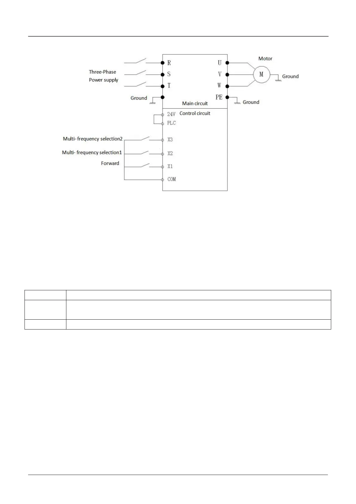
2. Inverter wiring diagram:
11.4 Communication mode controls the inverter
In some applications, the communication method is used to control the inverter, and the Kinco inverter
supports the Modbus protocol communication RTU mode. Communication mode control inverter start and
stop and frequency parameter settings are as follows:
Firstly, according to the actual motor on site, according to the motor parameters on the motor nameplate,
correctly set to the b0 group parameters of the inverter, and make the self-tuning, and then set the following
parameters.
1. Parameters setting:
A0.04 set 2, indicating that the inverter is in communication mode control.
The b3.00 setting should be consistent with the communication speed and data format of the
host computer.
B3.01 is set to the local address, which is the same as the address of the host computer.
The start and stop control register address of the inverter is 0X3200, and the frequency given register
address is 0X3201.
a) Inverter 30HZ operation: then 0X3200=455 (decimal)=1C7 (hexadecimal); 0X3201=3000
(decimal)=BB8 (hexadecimal).To run the inverter at 50Hz, set 0X3201=5000 (decimal)=1388 (hexadecimal).
b) Inverter deceleration stop: 0X3200=454 (decimal)=1C6 (hexadecimal).
2. Inverter wiring diagram:
 Loading...

