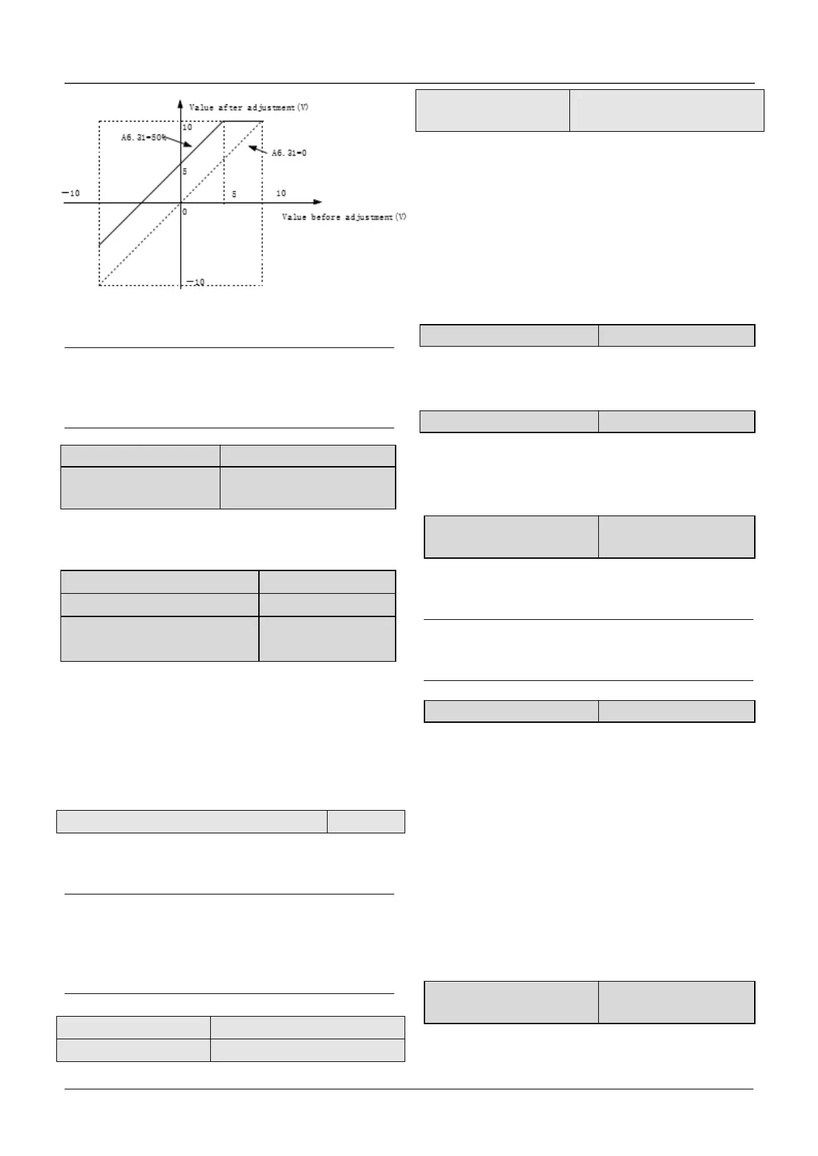
Fig.6-32 The relationship curve between analog
output and zero offset
Note:
The parameters of gain and zero offset calibration
affect the analog output all the time when it is
changing.
A6.35 Zero offset
calibration of AO2
The functions of analog output AO2 are totally the
same as AO1.
A6.38 Keyboard potentiometer
filter
A6.36 ~ A6.38 define the time constant of AI filter.
The longer the filter time, the stronger the
anti-interference ability, but the response will
become slower. The shorter the filter time, the
faster the response, but the anti-interference ability
will become weaker.
A6.39 Analog input zero offset calibration
0: Disable
1: Enable
Note:
Before the analog input zero offset calibration is
enable, it needs to make sure there is no wiring in
analog input terminal or the analog input terminal is
connected to GND.
A6.42 Keyboard
potentiometer gain
AI gain is used for the relationship between analog
input and internal value. When increasing the AI
gain, then the corresponding internal value will be
increased. When decreasing the AI gain, then the
corresponding internal value will be decreased.
Take AI1 for example, if the input AI1 is 10V but
detecting value of AI1 is 8V, increasing the AI1 gain
can make it to 10V.
This parameter defines the type of encoder.
0:ABZ incremental type
1~3:Reserved
A7.01 Number of pulses
per revolution of PG
A7.01 is used to set the number of pulses per
revolution of PG(PPR).
Note:
A7.01 must be set correctly when the drive run with
speed sensor, or the motor can’t run normally.
0:A phase lead B phase
1:B phase lead A phase
A phase lead B phase when motor run forward. B
phase lead A phase when motor run reverse. If the
direction which decided by the wiring sequence
between interface board and PG is the same as the
direction which decided by the wiring sequence
between drive and motor, then set this parameter
as 0 (Forwards),or set it as 1 (Reverse).
By changing this parameter, the user can change
the direction without re-wiring.
A7.03 Encoder signal filter
number
This parameter defines the filter number of
feedback speed.
 Loading...

